Optical measurement and inspection method and apparatus having enhanced optical path difference detection

a technology of optical path difference and inspection method, which is applied in the direction of instruments, optical elements, interferometers, etc., can solve the problems of increasing the use and complexity of optical structures, such as fiber optic cables, beam splitters, combiners and couplers,

Inactive Publication Date: 2003-11-25
XYRATEX CORP
View PDF4 Cites 14 Cited by
  • Summary
  • Abstract
  • Description
  • Claims
  • Application Information

AI Technical Summary

Problems solved by technology

Optical structures, such as fiber optic cable, beam splitters, combiners and couplers, as well as active optical components are presently increasing in use and complexity.

Method used


Image

  • Optical measurement and inspection method and apparatus having enhanced optical path difference detection
  • Optical measurement and inspection method and apparatus having enhanced optical path difference detection
  • Optical measurement and inspection method and apparatus having enhanced optical path difference detection

Examples


Embodiment Construction

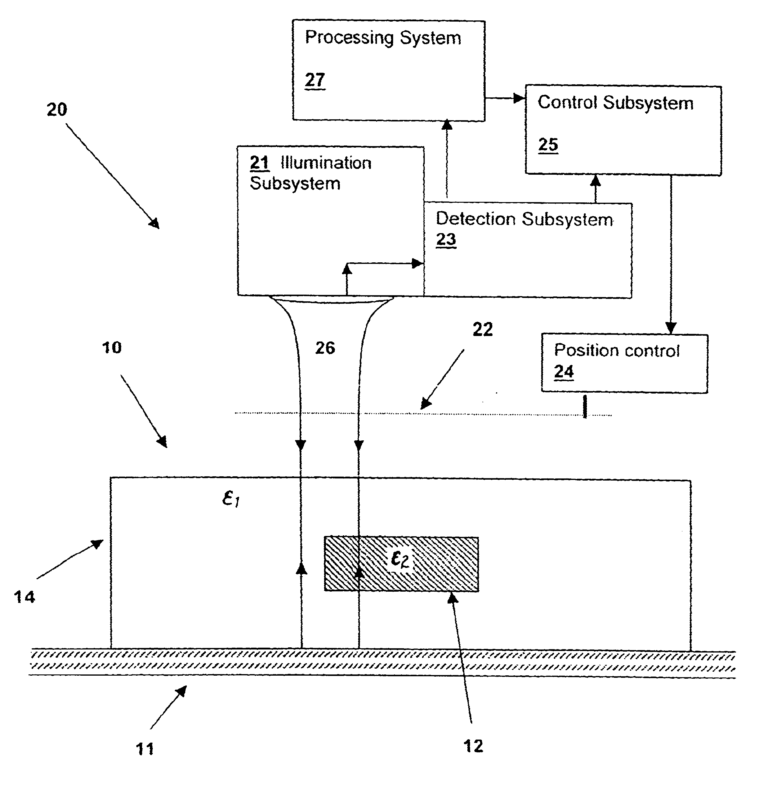
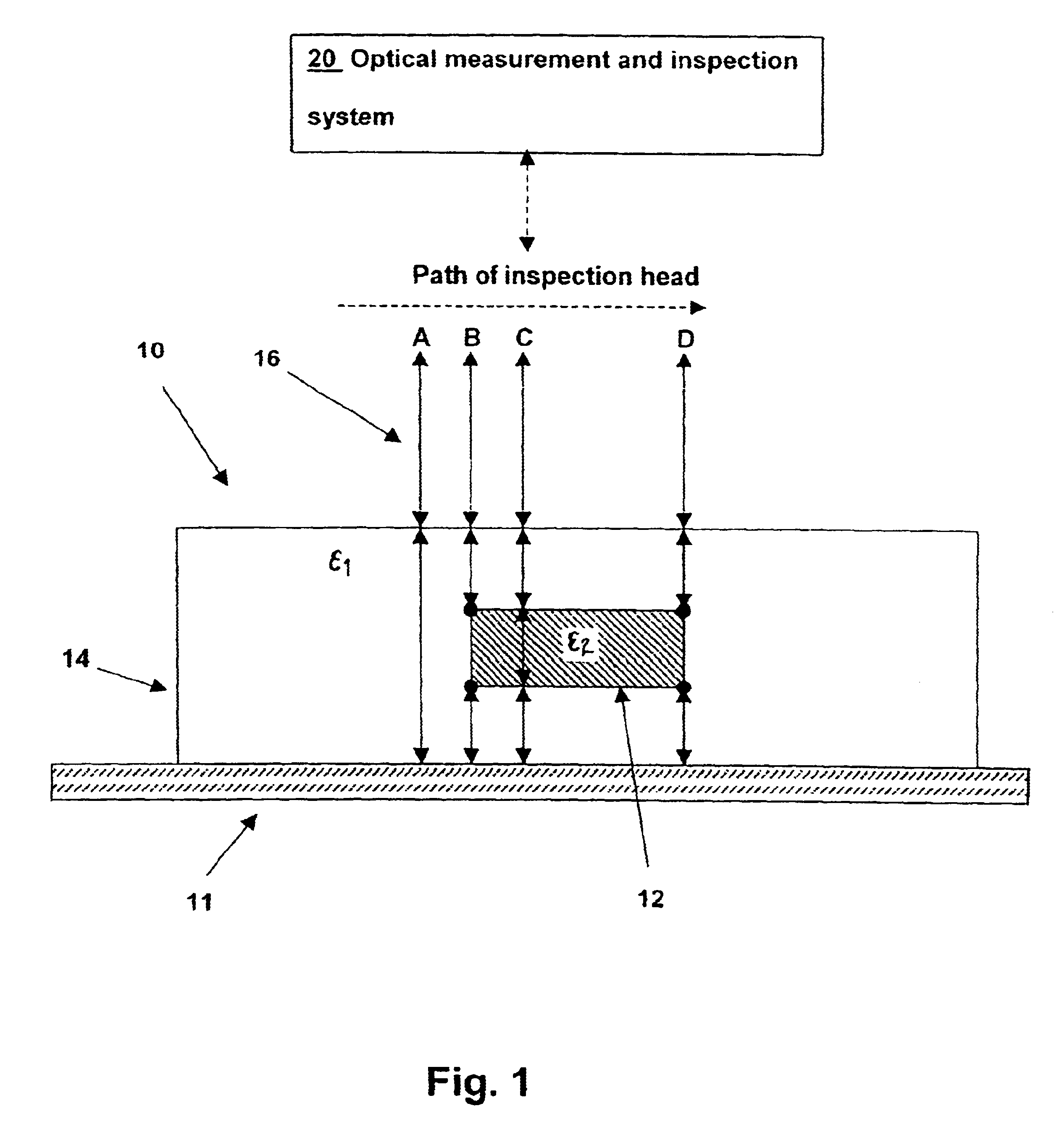
With reference now to the figures, and particularly to FIG. 1, a cross section of an optical device 10 under test by an apparatus in accordance with an embodiment of the invention is depicted. A core 12 having a refractive index of n.sub.2 is embedded within a cladding 14 having a refractive index of n.sub.1. Refractive index n.sub.2 is generally higher than refractive index n.sub.1, so that the optical field is generally contained within the core 12, but this is not a restriction on the operation of the present invention. A priori knowledge of the ranges of variation in refractive indices and the sizes of features such as core 12 may be used within the system of the present invention to avoid ambiguities and to optimize the operating point of the system of the present invention. A reflective substrate 11 is necessary for operation of the present invention and may either be part of optical device 10 as depicted, or (for transparent optical devices) may be placed beneath optical devi...


PUM

PropertyMeasurementUnit
optical path lengthaaaaaaaaaa
optical measurementaaaaaaaaaa

Abstract

An optical measurement and inspection method and apparatus having enhanced path length detection uses a Fabry-Perot cavity to increase the phase detection sensitivity for light reflected from optical structures within a device under inspection. A partially reflective surface is inserted between an illumination subsystem and the device under inspection and the position of the partially reflective surface may be adjusted by a positioner to create the Fabry-Perot cavity between one or more surfaces within the device under inspection. The detection of phase changes is improved, providing improved sensitivity to optical path differences produced by structures within the device under inspection.

Description

1. Field of the InventionThis invention relates to optical inspection and measuring systems, and more specifically, to an optical system incorporating a resonator to enhance detection of optical path differences in structures under inspection.2. Description of the Related ArtOptical structures, such as fiber optic cable, beam splitters, combiners and couplers, as well as active optical components are presently increasing in use and complexity. Optical systems are desirable for secure and high speed processing and communications, so manufacture of optical structures is increasing due to market demands.Recently, planar optical structures have been developed that incorporate optical devices, fiber interconnects and connectors within a thick layer mounted on a substrate. Planar optical structures enable the manufacture of high-density optical processing and telecommunication systems.In the manufacturing process, it is necessary to inspect and measure planar optical structures, to determ...

Claims


Application Information

Patent Timeline
Patent Type & Authority Patents(United States)
IPC IPC(8): G01B9/02G02B26/00
CPCG02B26/001G01B9/02018G01B9/02024G01B2290/25
Inventor CLARK, BRYAN KEVIN
Owner XYRATEX CORP
Why Eureka
Try Eureka