Input device using tapping sound detection
a technology of input device and sound detection, which is applied in the field of input device, can solve the problems of difficult one-person operation of the computer, sometimes not going well communication between the presenter and the operator, etc., and achieve the effect of convenient computer operation
- Summary
- Abstract
- Description
- Claims
- Application Information
AI Technical Summary
Benefits of technology
Problems solved by technology
Method used
Image

Examples
first embodiment
A.
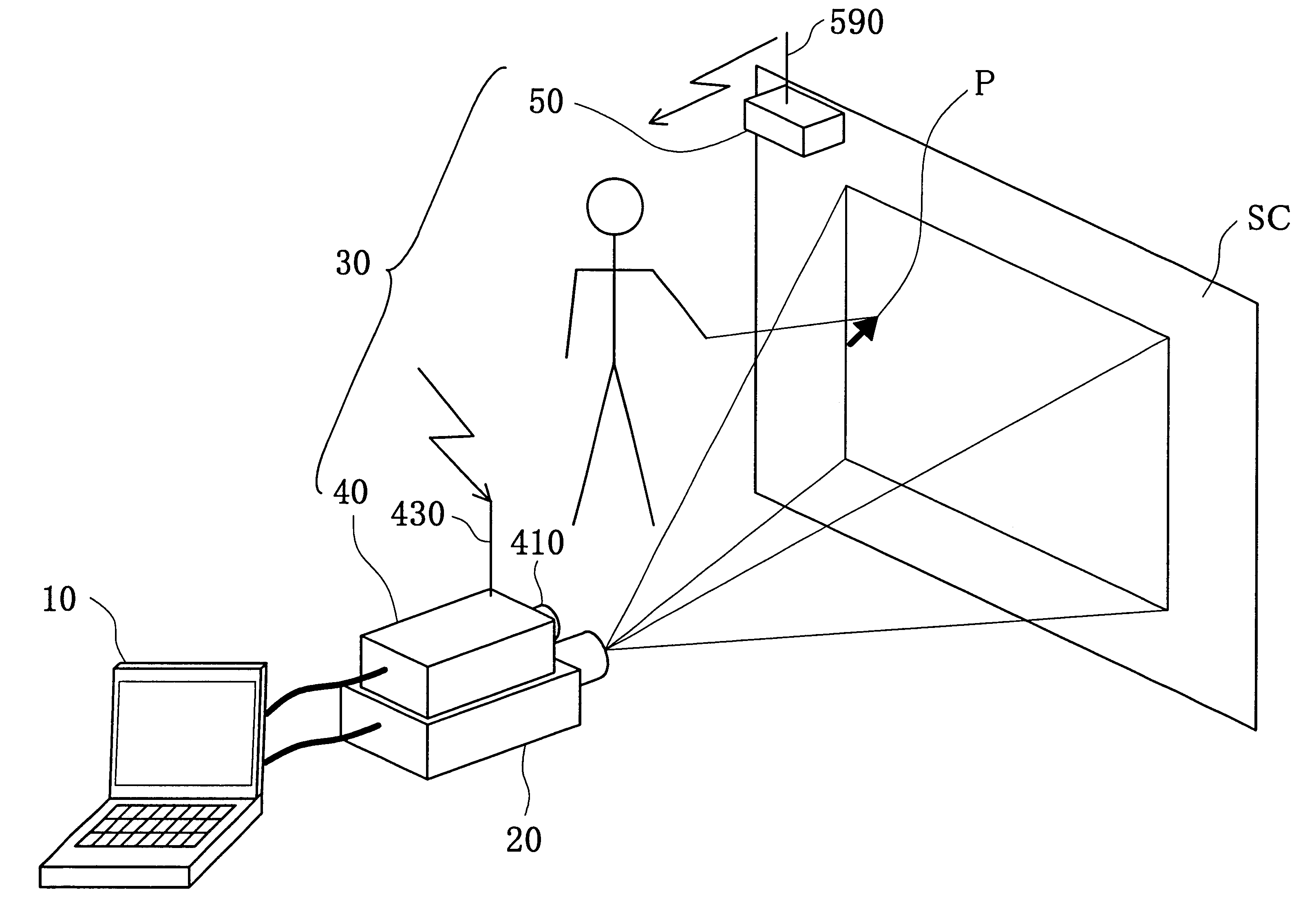
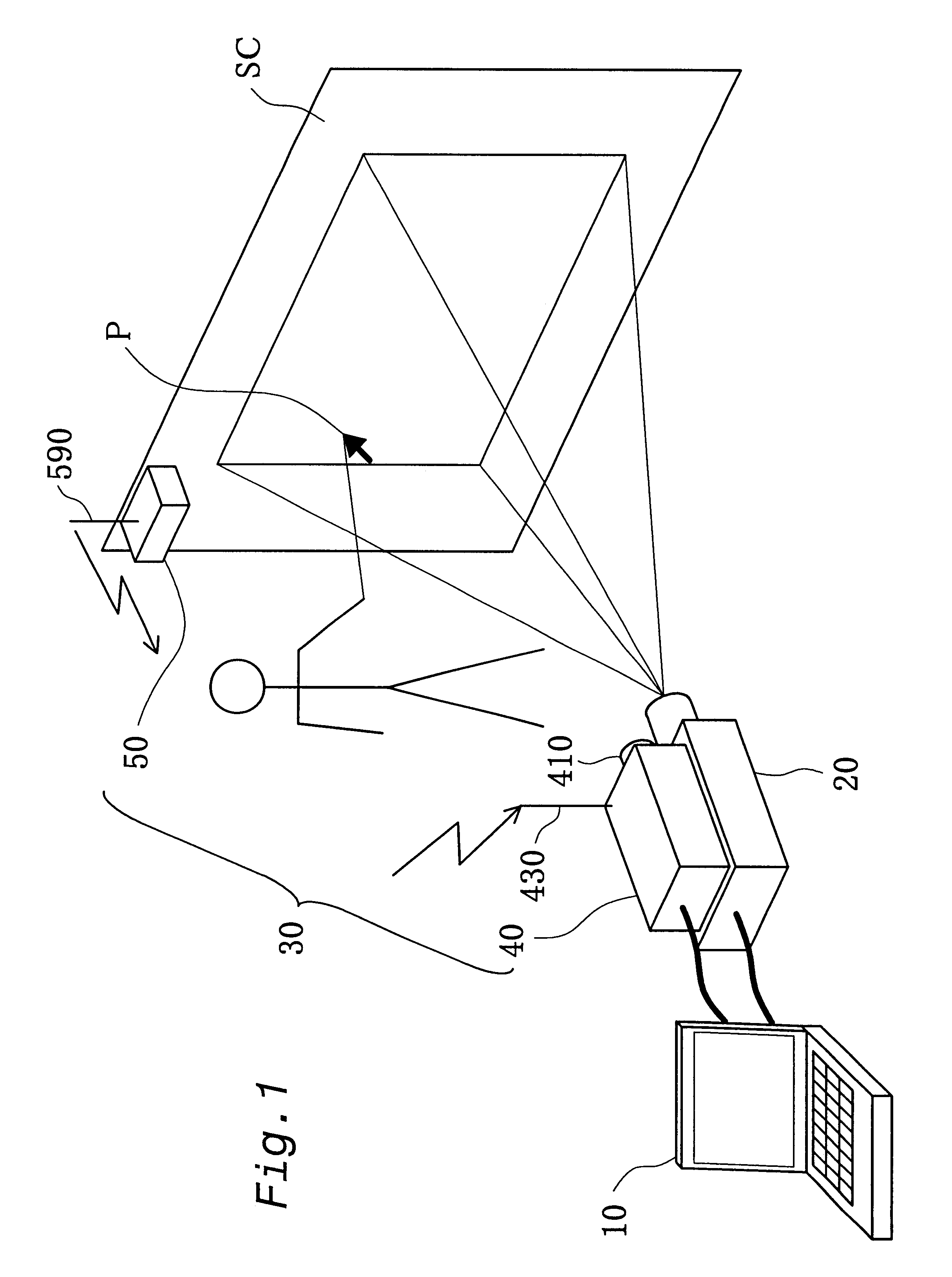
FIG. 1 shows the configuration of a computer system including the pointing device in a first embodiment of the present invention. The computer system includes a computer 10, which functions as an image supply device, a projector 20, which functions as a display device, and a pointing device 30. The computer system constitutes the image display system pertaining to the present invention. An image input terminal of the projector 20 is connected to an image output terminal of the computer 10 via a video cable. The projector 20 projects images supplied from the computer 10 onto the screen SC for display.
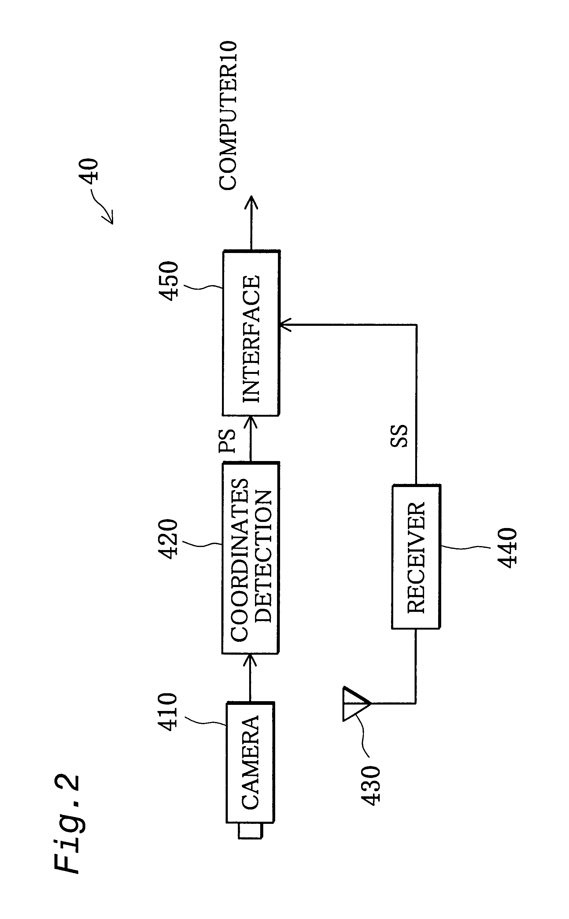
The pointing device 30 includes a pointing device signal generator 40 and a tapping sound processor 50. The pointing device signal generator 40 constitutes a position determination device and a pointing data output device of the present invention, and the tapping sound processor 50 constitutes an acoustic input device of the present invention. The tapping sound processor 50 is mounted ...
second embodiment
B.
FIG. 6 shows the configuration of a computer system including the pointing device in a second embodiment of the present invention. The computer system has a different configuration in the pointing device 30 of the computer system of the first embodiment shown in FIG. 1, but the configuration for the other components are identical with the first embodiment and therefore will not be explained.
The pointing device 30A includes a pointing device signal generator 40A and a tapping sound processor 50A. FIG. 7 shows the functional configuration of the pointing device signal generator 40A. FIG. 8 show the functional configuration of the tapping sound processor 50A. The pointing device signal generator 40A is the same as the pointing device signal generator 40 of the first embodiment other than that the reception antenna 430 and the receiver 440 shown in FIG. 2 are replaced with a receiver 430A and an amplifier 440A. The tapping sound processor 50A is the same as the tapping sound processor...
third embodiment
C.
FIG. 10 shows the configuration of a computer system including the pointing device in a third embodiment of the present invention. The computer system of the third embodiment also has a different configuration in the pointing device 30 of the computer system of the first embodiment shown in FIG. 1, but the configuration for the other components are identical with the first embodiment and therefore will not be explained.
The pointing device 30D includes a pointing device signal generator 40D and a tapping sound processor 50D. FIG. 11 shows the functional configuration of the pointing device signal generator 40D. FIG. 12 shows the functional configuration of the tapping sound processor 50D. The pointing device signal generator 40D differs from that in the first embodiment in that the receiver 440 shown in FIG. 2 is replaced with a transmitter / receiver 440D and a modulator / demodulator 445, so that two-way communication may be performed with the tapping sound processor 50. Similarly, t...
PUM
 Abstract
Description
Claims
Application Information
PatSnap Eureka turns technology decisions into work you can execute. Powered by our Innovation Knowledge Graph, it runs expert workflows across engineering, life sciences, materials and intellectual property. Get your review-ready output in minutes.


