Method of optimizing part transfer motion

Inactive Publication Date: 2003-12-09
FORD MOTOR CO
View PDF4 Cites 26 Cited by
  • Summary
  • Abstract
  • Description
  • Claims
  • Application Information

AI Technical Summary

Problems solved by technology

This requires frequent and continuing adjustment of the setup for the motion path over an ext

Method used


Image

  • Method of optimizing part transfer motion
  • Method of optimizing part transfer motion
  • Method of optimizing part transfer motion

Examples


Embodiment Construction

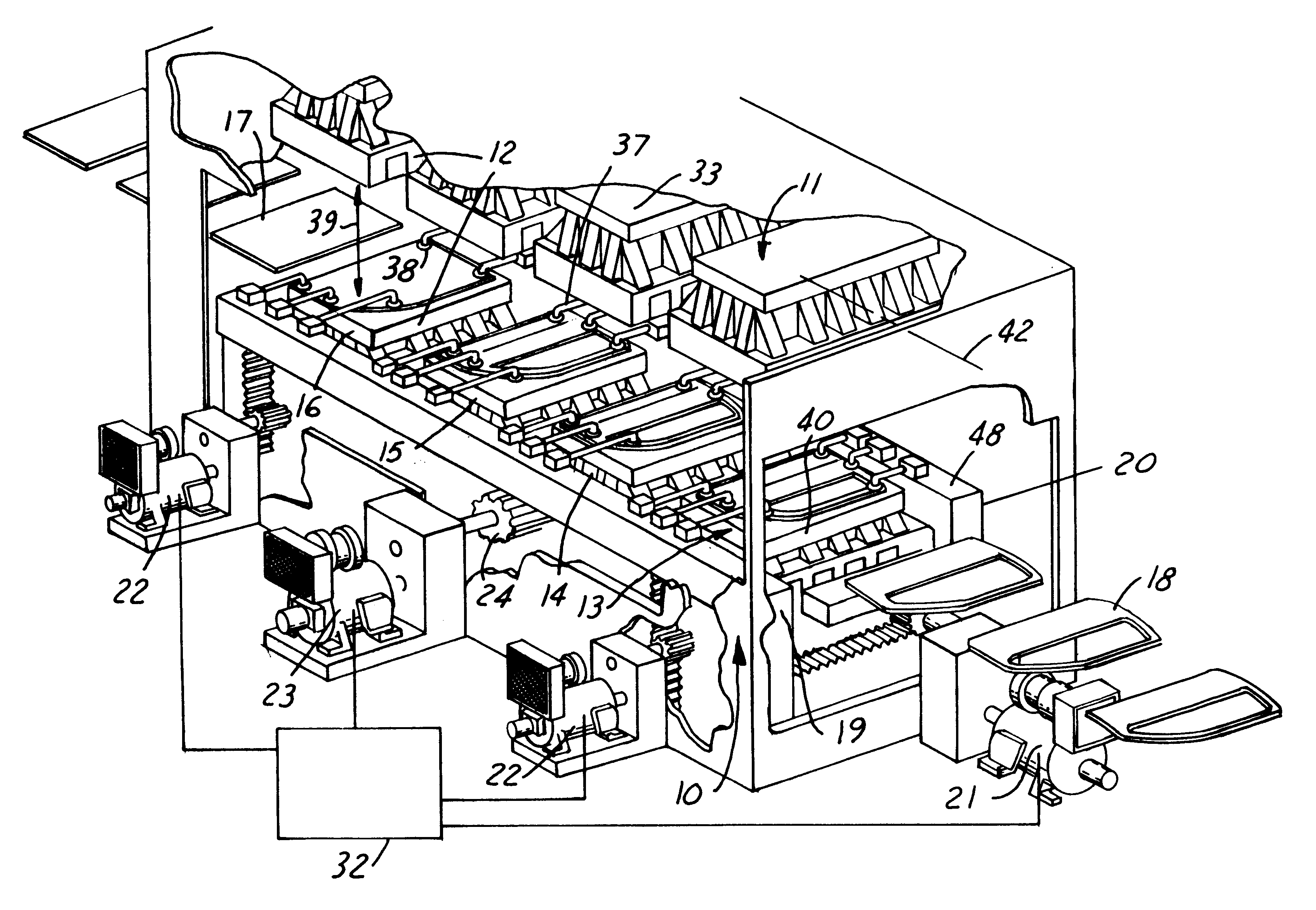
Stamping presses that use programmable transfer devices to move panels or parts between stamping workstations, fall generally into the following categories: transfer feedrail mechanisms for a single press having multiple workstations; dual axis pick and place devices for adjacent presses; and robots for multiple-presses in any arrangement.

Programmable Transfer Device

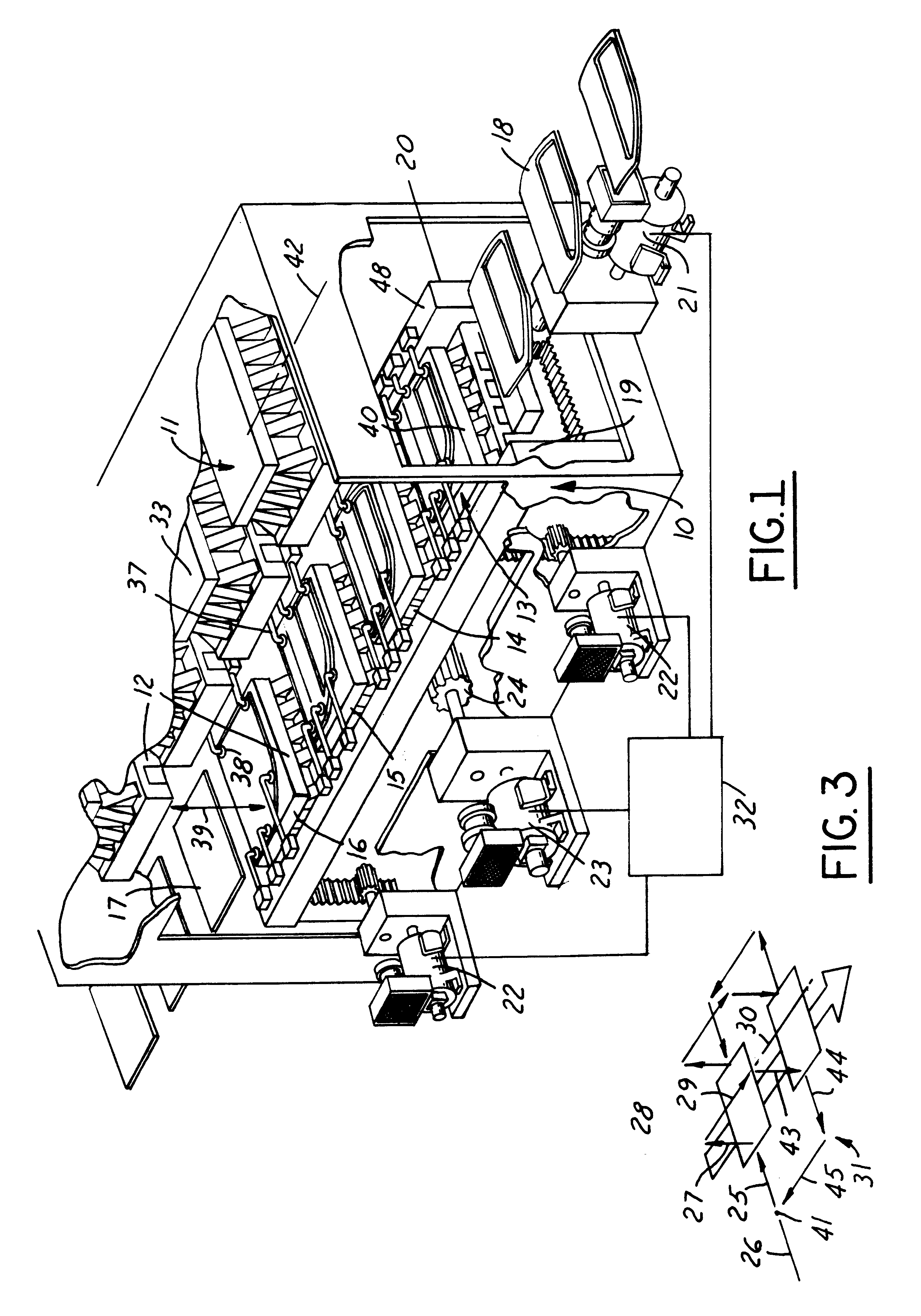
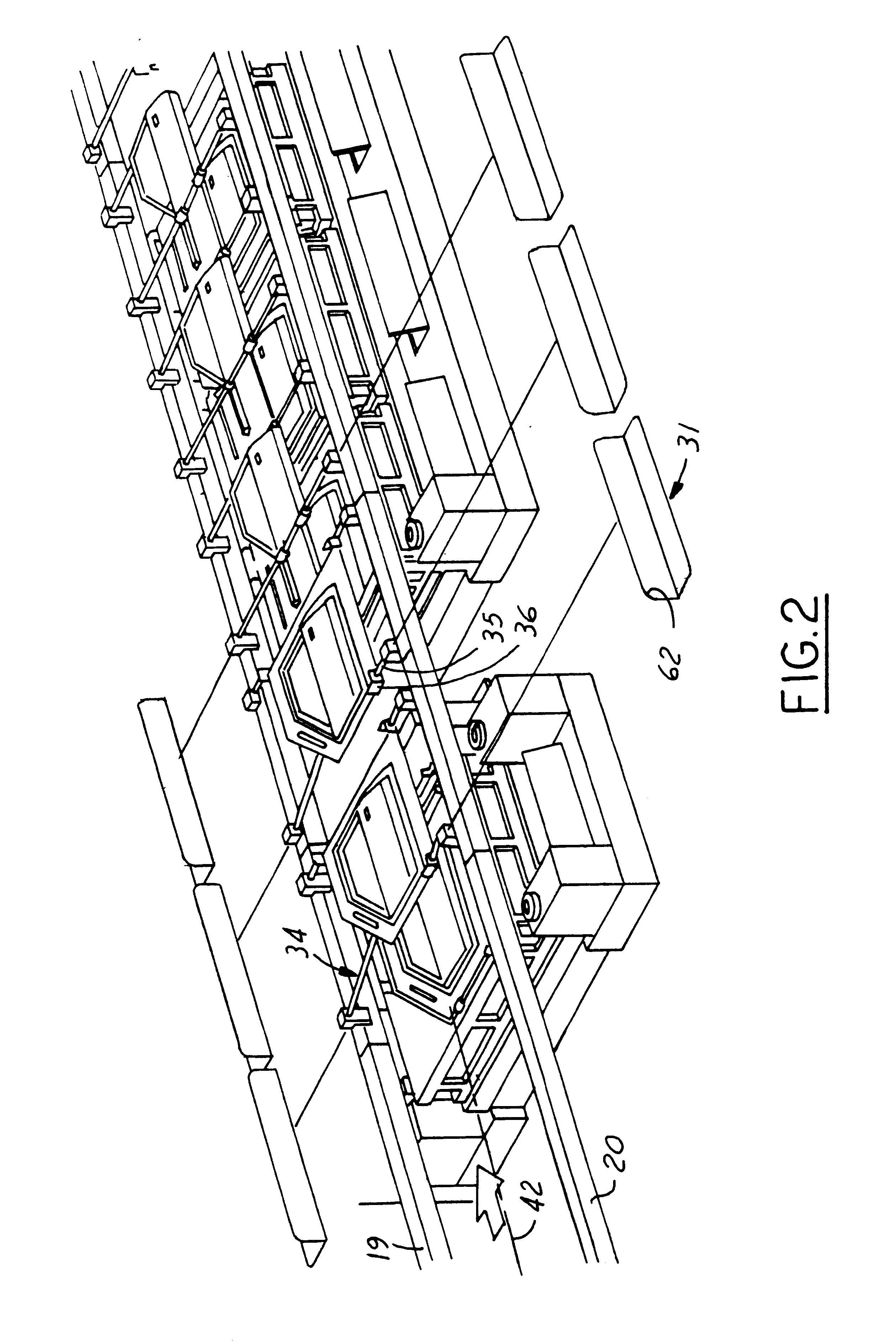
As shown in FIG. 1, a part transfer device 10, for a large single press 11 having multiple sets of dies 12 located at in-line workstations 13,14,15,16, carries stamping panels 17 from die set to die set; the panels 17 will be progressively drawn, stretched, trimmed or pierced at such workstations to form a finished part 18 within the single press 11. The transfer device shown is an electronic transfer feed rail system; it usually comprises a pair of transfer rails 19, 20 running the length of the press to support and convey the panels 17 from die operation to die operation. The rails are simultaneously moved in three axi...


PUM


Abstract

A method is disclosed that adjusts motion path parameters of a programmable part transfer device having part engaging tooling; the device is used to transfer parts between workstations of one or more cyclical stroking devices dependent on a rotary drive clock. The method comprises: setting up a non-linear analytical regression math model of the motion path of the part engaging tooling coordinated with the motions of the cyclically stroking device, the math model having motion path parameters at least for path speed, angular duration of path segments as a function of the drive clock, part stability, and dynamic freedom for said tooling within the stroking machine; initializing the math model with a first selected set of motion parameters; iteratively solving the math model to determine an optimum combination of at least path speed and part stability when transferring parts during each rotation of the drive clock, such transfer being devoid of any physical interference with the cyclically stroking device.

Description

1. Technical FieldThis invention relates to the technology of physically moving parts between stations for carrying out sequential manufacturing stages, and, more particularly, to computer based methodology that permits manufacturing engineers to select motion set-up parameters that optimize production rate and manufacturing equipment life.2. Discussion of the Prior ArtIn the sequential stamping of sheet metal panels to form completed stamped parts, the motion transfer path for the panels is one of the most critical factors affecting manufacturing productivity. Motion path planning is commonly done on site in an ad hoc fashion. This requires frequent and continuing adjustment of the setup for the motion path over an extended period of use of the motion path, which adjustments may or may not enhance productivity. Typically the motion path becomes degraded as new or different physical part characteristics are experienced or newer tooling is substituted.Applicant is unaware of any avai...

Claims


Application Information

Patent Timeline
IPC IPC(8): G06F19/00G05B19/418
CPCG05B19/41825G05B2219/45137G05B2219/43114G05B2219/31274Y02P90/02
Inventor XU, DIANELIASI, EVANGELOSKARIMALIS, JOHN THOMASELDEEB, YASSER MOHAMMED
Owner FORD MOTOR CO
Why Eureka
Try Eureka