Method and apparatus for a thermal control system based on virtual temperature sensor

a virtual temperature sensor and control system technology, applied in the field of data processing systems, can solve the problems of system cooling difficulty, system heat loss, and inconvenient or ideal locations for temperature sensors, and achieve the effect of improving the efficiency of temperature control systems and improving the accuracy of temperature control systems

Active Publication Date: 2008-02-07
APPLE INC
View PDF17 Cites 122 Cited by
  • Summary
  • Abstract
  • Description
  • Claims
  • Application Information

AI Technical Summary

Benefits of technology

[0009]Methods and apparatuses for providing a virtual temperature sensor to control temperatures or other parameters in a data processing system are described here. Some embodiments of the present invention are summarized in this section.

Problems solved by technology

As the operating power consumptions of the individual components of computer system creep upwards, the thermal budgets of the computer systems have become tighter.
The systems have become more difficult to cool.
It is now becoming a challenge to design a computer system to run continuously at the worst-case thermal load while pursuing other high performance goals, such as high computing power, compactness, quietness, better battery performance, etc.
One of the critical issues in thermal management system is the location of the temperature sensor since the system temperature distribution is likely not uniform, and therefore the temperature sensor is typically best located in the hottest location to assure that the whole system is under the temperature limit.
Current computer systems do not provide convenient or ideal locations for temperature sensors.
A further temperature control problem associated with current computer systems is the variation of hottest temperature locations, occurring due to the optional components that can be dynamically inserted or removed.
Each system configuration has its own ideal location for a temperature sensor, and therefore the multiple system configurations make an optimum temperature sensor placement difficult and often impractical.
A thermal control system which does not have an accurate way to measure a “system” temperature is forced to assume the worst case thermal scenario.
For a system where the optimum temperature sensor location changes with user's configurations, a thermal control system is blind to certain critical component temperatures and certain system configurations, and is forced to assume the worst, resulting in a reduced performance or an overcooled system with unpleasant acoustic output (e.g. the noise of a fan) due to excessive cooling operations.

Method used


Image

  • Method and apparatus for a thermal control system based on virtual temperature sensor
  • Method and apparatus for a thermal control system based on virtual temperature sensor
  • Method and apparatus for a thermal control system based on virtual temperature sensor

Examples


Embodiment Construction

[0029]The following description and drawings are illustrative of the invention and are not to be construed as limiting the invention. Numerous specific details are described to provide a thorough understanding of the present invention. However, in certain instances, well known or conventional details are not described in order to avoid obscuring the description of the present invention. References to one or an embodiment in the present disclosure are not necessarily references to the same embodiment; and, such references mean at least one.

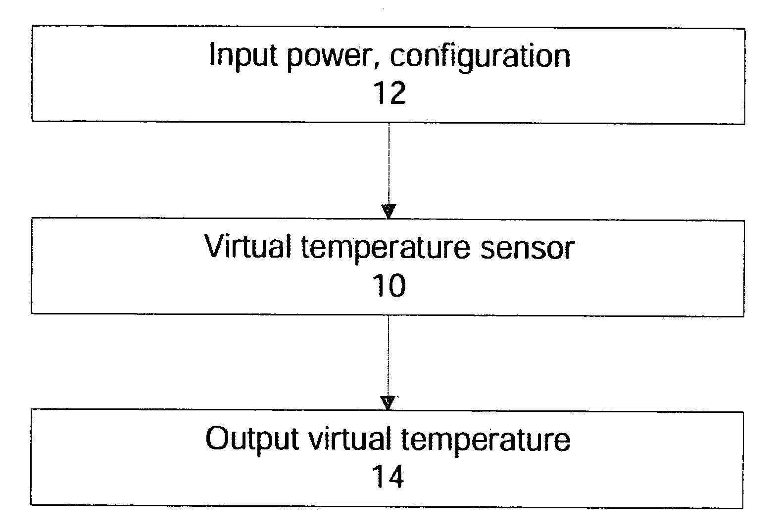
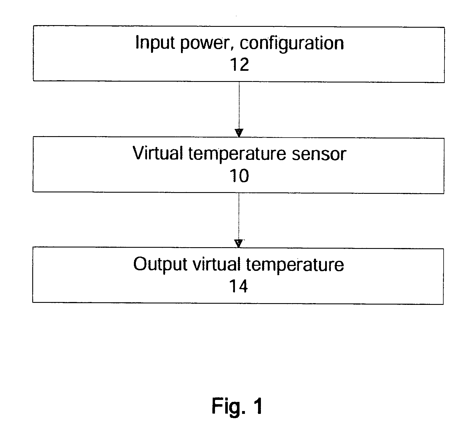
[0030]In one aspect of an embodiment of the present invention, a data processing system includes a virtual temperature sensor to provide a system temperature to accommodate different system configurations. The virtual temperature sensor provides temperature information from calculations instead of a physical temperature sensor, although these calculations may use either current or stored temperature readings from physical temperature sensors. This ...


PUM

PropertyMeasurementUnit
temperatureaaaaaaaaaa
thermal characteristicsaaaaaaaaaa
poweraaaaaaaaaa

Abstract

Methods and apparatuses for providing virtual temperature sensor to control temperatures in a data processing system. In one aspect, a data processing system includes a virtual temperature sensor to provide system temperature for different system configurations, and a controller coupled to the sensor to control operations of the data processing system according to the virtual temperature. The virtual temperature sensor typically derives the temperature of a particular configuration of the data processing system using mathematical models or one or more operating parameters of the data processing system. In one example, the mathematical models include a characterization table which provides the measured temperature data from various system configurations. These measurements are performed with temperature sensors positioned in ideal locations for different configuration, and are preprocessed to provide the virtual temperature computation. The characterization table also includes thermal characteristics, such as thermal time constant and thermal resistance, of the critical components at multiple thermal control states.

Description

[0001]This application is related to and claims the benefit of the filing date of U.S. Provisional Patent Application No. 60 / 835,643, filed on Aug. 4, 2006.FIELD OF THE INVENTION[0002]At least some embodiments of the present invention relate generally to data processing systems, and more particularly but not exclusively to the management of temperatures in data processing systems.BACKGROUND[0003]Traditionally, computer systems are designed to be able to continuously run a fairly worst-case thermal load corresponding to a worst-case workload. Designs according to such a continuous worst-case load have never been much of a problem, because traditionally the individual components have had modest operating power consumptions and the computer systems have had considerable cooling capacity so that the systems could sustain the load fairly naturally.[0004]As the operating power consumptions of the individual components of computer system creep upwards, the thermal budgets of the computer s...

Claims


Application Information

Patent Timeline
Patent Type & Authority Applications(United States)
IPC IPC(8): G01K13/00
CPCY02B60/1275G06F1/206Y02D10/00
Inventor MILLET, TIMOTHY JOHN
Owner APPLE INC
Why Eureka
Try Eureka