
System and method for design and control of engineering systems utilizing component-level dynamic mathematical model

a dynamic mathematical model and engineering control technology, applied in flow control using electric means, ratio control, instruments, etc., can solve the problems of reducing the accuracy reducing the complexity of engineering control systems, and reducing the tolerance of components, so as to minimize the error vector

Active Publication Date: 2011-03-31
RTX CORP
View PDF26 Cites 126 Cited by
  • Summary
  • Abstract
  • Description
  • Claims
  • Application Information

AI Technical Summary

Benefits of technology

[0005]This disclosure concerns a system and a method for design and control of an apparatus. The system utilizes a control law to control actuators that position control elements of the apparatus, as a function of a model output vector generated by a component-level physics-based mathematical model of the apparatus. The system also includes diagnostics and fault detection / accommodation software modules.
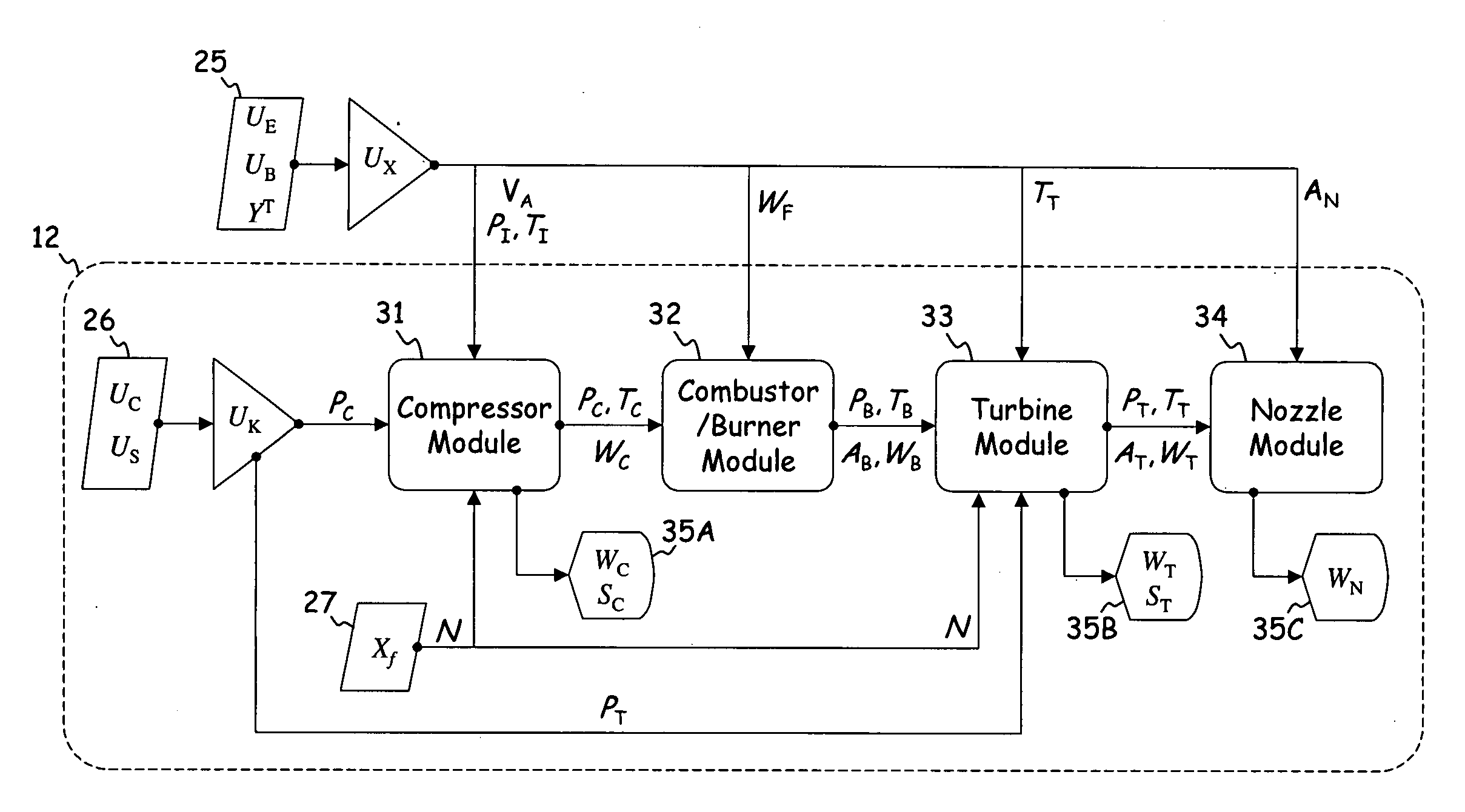
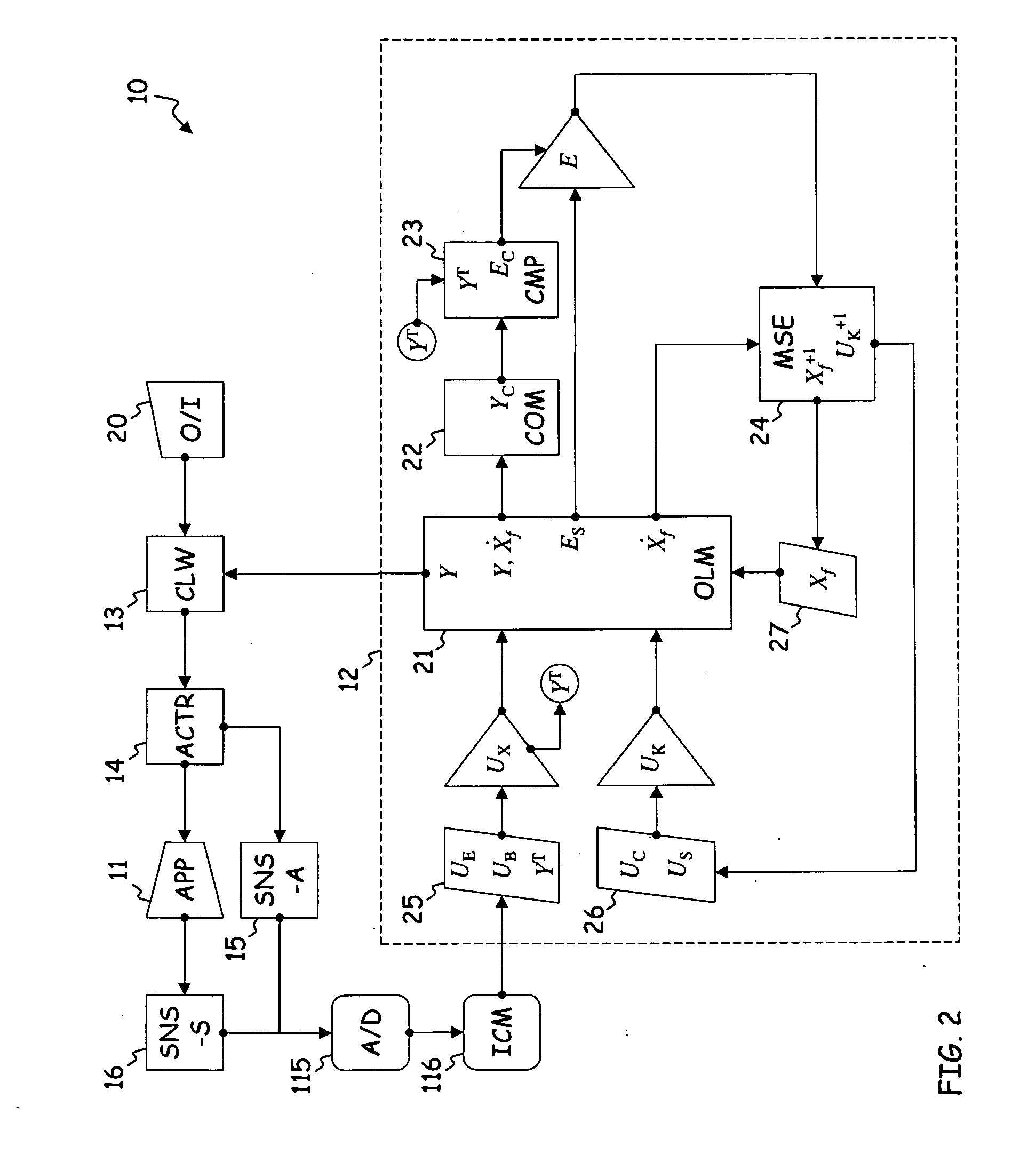
[0006]The model comprises mathematical descriptions of interconnected components and constraints that combine to produce the output vector and a physics state derivative, as a function of a constraint input and an external input vector. The constraint output is related to internal system, and the external input vector is related to effector / actuator states and boundary conditions of the apparatus. A comparator checks a subset of the output vector against a “truth” vector represented by measured or high fidelity modeled data, in order to generate an error vector. The discrete model state estimator synthesizes (estimates) next time step values of the state vector, including both constraint and physics subsets, such that the error vector is minimized.
[0007]In the case of a gas turbine or other flow-processing apparatus, the method provides means for controlling physics states, including rotational states, for given working fluid flow conditions at an inlet and an outlet. The method also provides means for adjusting the position of control elements along the working fluid flow, using actuation mechanisms and a digital control system built around the dynamic component-level mathematical model.

Problems solved by technology

Across a broad range of industries, modern engineering systems are characterized by marked increases in complexity and simultaneous decreases in component tolerances.
As a result, engineering control systems are subject to greater operational demands, which require more sophisticated and detailed modeling techniques.

Method used


Image

  • System and method for design and control of engineering systems utilizing component-level dynamic mathematical model
  • System and method for design and control of engineering systems utilizing component-level dynamic mathematical model
  • System and method for design and control of engineering systems utilizing component-level dynamic mathematical model

Examples


Embodiment Construction

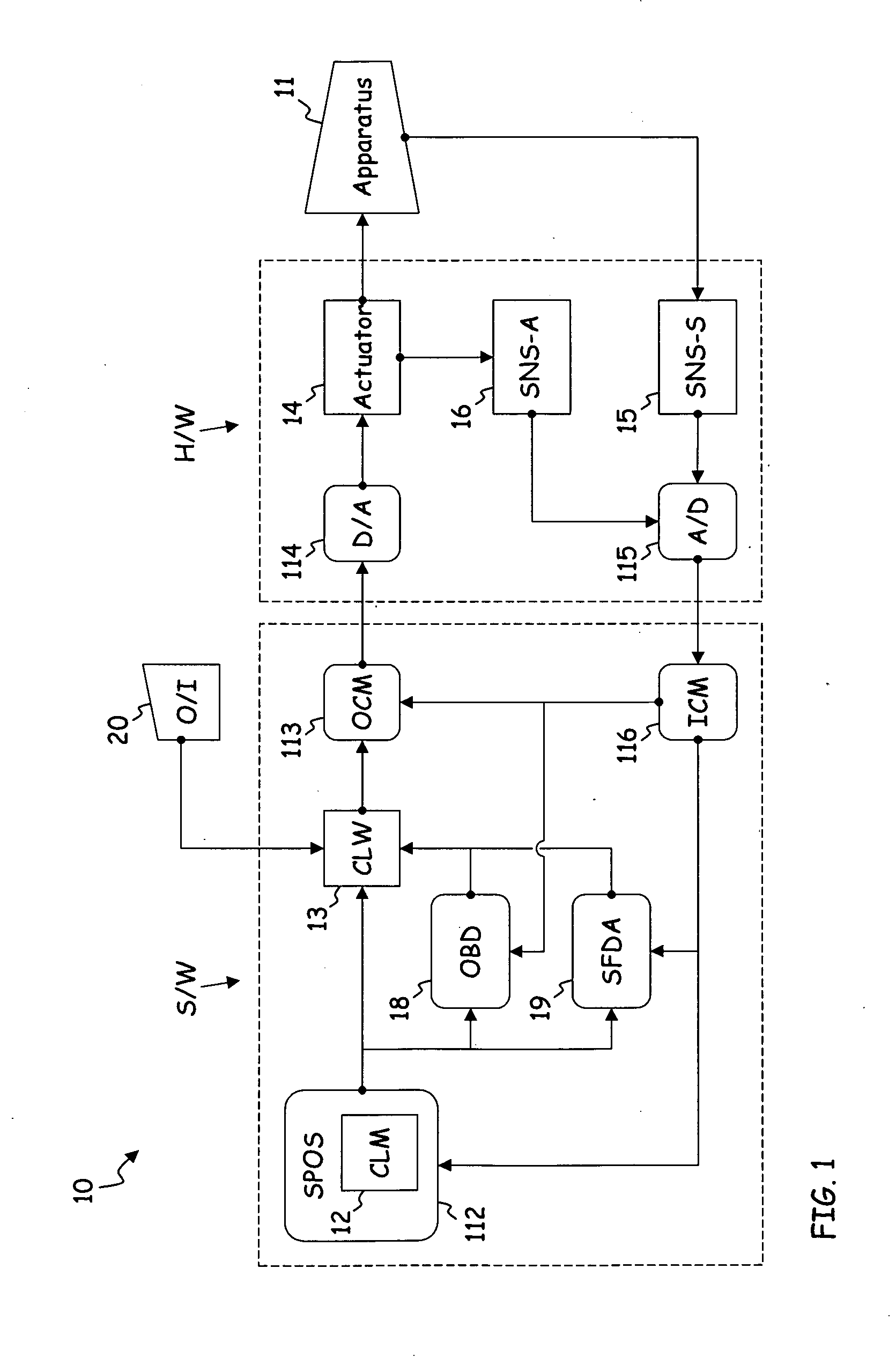
[0013]FIG. 1 is a schematic diagram of digital control system 10 for apparatus 11. Control demands for apparatus 11 are generated by operator interface (I / F) 20, and satisfied by utilizing the components of system 10 to control apparatus (or engineering system) 11.

[0014]In general, system 10 includes at least some of the following software (S / W) modules: system parameter on-board synthesis (SPOS) module 112, control law (CLW) 13, on-board diagnostics (OBD) module 18, sensor fault detection and accommodation (SFDA) module 19, output conditioning module (OCM) 113, and input conditioning module (ICM) 116. These modules are incorporated in a “black box” type processor assembly mounted proximate apparatus 11, or in a number of individual processors. SPOS 112 is build around a component-level mathematical model of apparatus 11, also referred to as closed loop model (CLM) 12, such that CLM 12 is a subset of SPOS 112. System 10 also incorporates at least some of the following hardware (H / W)...


PUM


Abstract

A control system comprises a controller for positioning an actuator in a working fluid flow and a model processor for directing the controller as a function of a model feedback. The model processor comprises an output module, a comparator and an estimator. The output module generates the model feedback as a function of a constraint, a model state and a model input describing fluid parameters measured along the working fluid flow. The comparator generates an error by comparing the model feedback to the model input. The estimator generates the constraint and the model state, such that the error is minimized.

Description

STATEMENT OF GOVERNMENT INTEREST[0001]Subject matter disclosed in this application was produced with U.S. Government support under Contract No. N00019-02-C-3003, awarded by U.S. Navy. The U.S. Government may have certain rights in this invention.BACKGROUND OF THE INVENTION[0002]The subject matter of this application relates generally to the design and control of engineering systems. Across a broad range of industries, modern engineering systems are characterized by marked increases in complexity and simultaneous decreases in component tolerances. As a result, engineering control systems are subject to greater operational demands, which require more sophisticated and detailed modeling techniques.[0003]Fluid-based engineering systems provide a range of relevant examples. These include gas turbine engines for aviation and power generation, HVAC&R (heating, ventilation, air-conditioning and refrigeration), fuel cells, and other, more generalized fluid processing systems for hydrocarbon ...

Claims


Application Information

Patent Timeline
Patent Type & Authority Applications(United States)
IPC IPC(8): G05B13/04G05D7/06
CPCG05B17/02
Inventor KARPMAN, BORISMEISNER, RICHARD P.LACOUR, MARK E.
Owner RTX CORP
Learn More