Video Motion Detection Method and Alert Management

a motion detection and video technology, applied in the field of video monitoring, can solve the problems of not being able to visually monitor multiple camera video feeds for each customer, not being able to monitor these cameras themselves or typically even have access, and reducing the number of alerts or false alarms.

Inactive Publication Date: 2016-02-11
HOGG WILLIAM DAYLESFORD +1
View PDF11 Cites 126 Cited by
  • Summary
  • Abstract
  • Description
  • Claims
  • Application Information

AI Technical Summary

Benefits of technology

[0010]When the user is notified that a motion event has been detected, the user would then view the video clip associated with that motion event and based on that observation, choose one of several responses including but not limited to: doing nothing, instructing the camera to ignore all motion events for a period of time or instructing the camera to update its motion detection reference based on this new event. If the user instructs the camera to update its motion detection reference based on this motion event, the camera would then learn to respond to future similar motion events by comparing the new motion event description with the updated motion detection reference. Through this iterative process, the camera system refines its ability to respond to new motion events in a manner that the individual user desires. This in turn greatly reduces the number of alerts or false alarms the user must address.

Problems solved by technology

Most security companies have also started to market monitoring cameras to homeowners; however they don't monitor these cameras themselves or typically even have access to the video feeds.
While privacy concerns are a major issue, each monitor center has thousands of customers and cannot possibly visually monitor multiple camera video feeds for each customer.
They would also have no way of knowing who should be in your home and when.
However despite these improvements, motion detection with consumer grade cameras still generate far too many false alarms to be useful and as a result this feature is typically not used.

Method used


Image

  • Video Motion Detection Method and Alert Management
  • Video Motion Detection Method and Alert Management
  • Video Motion Detection Method and Alert Management

Examples


Embodiment Construction

A. Video Camera and Analytics Processing

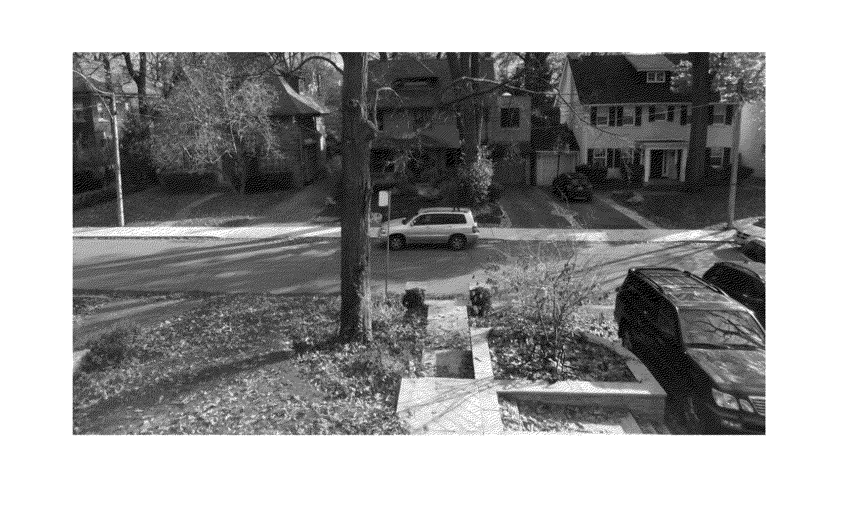
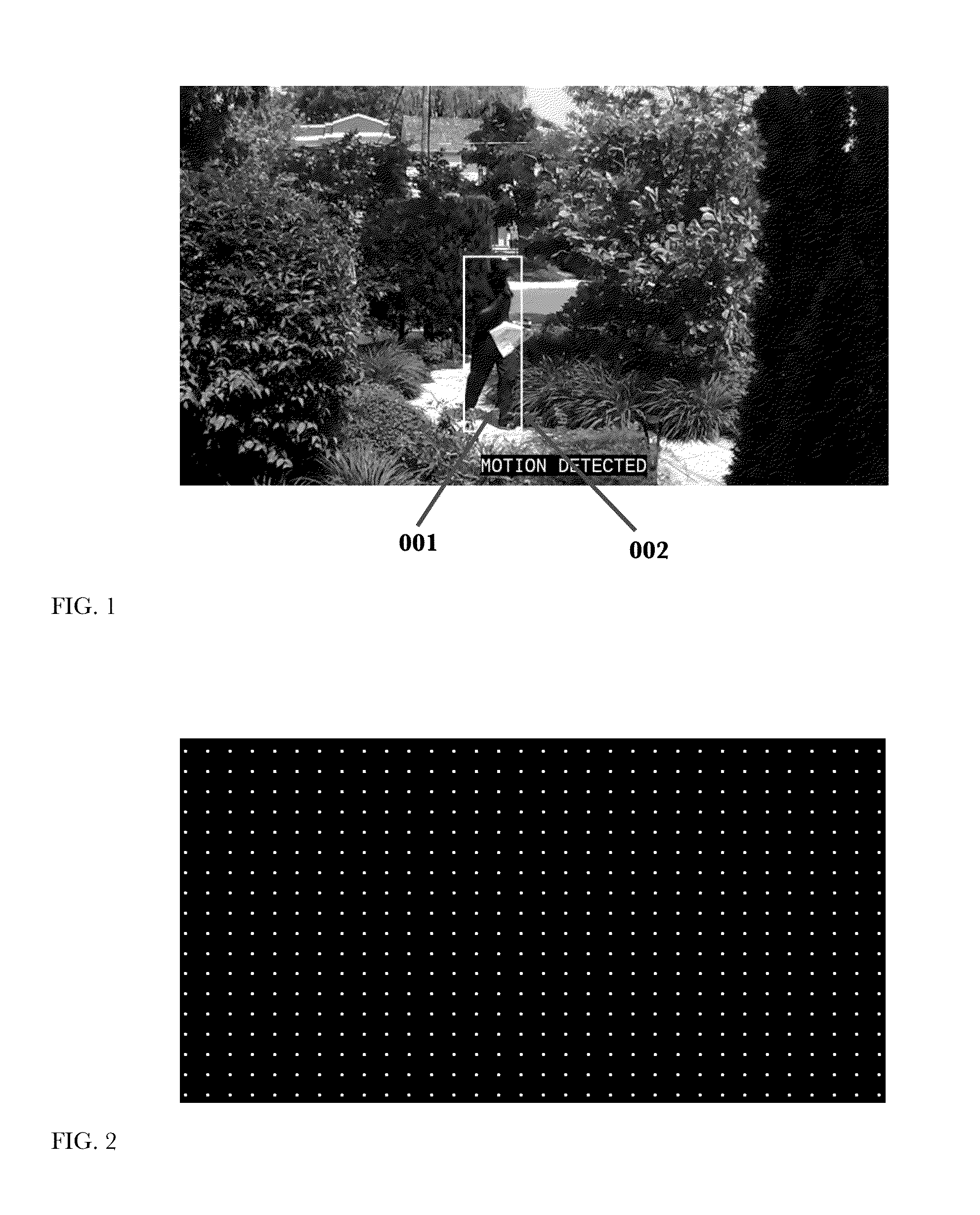
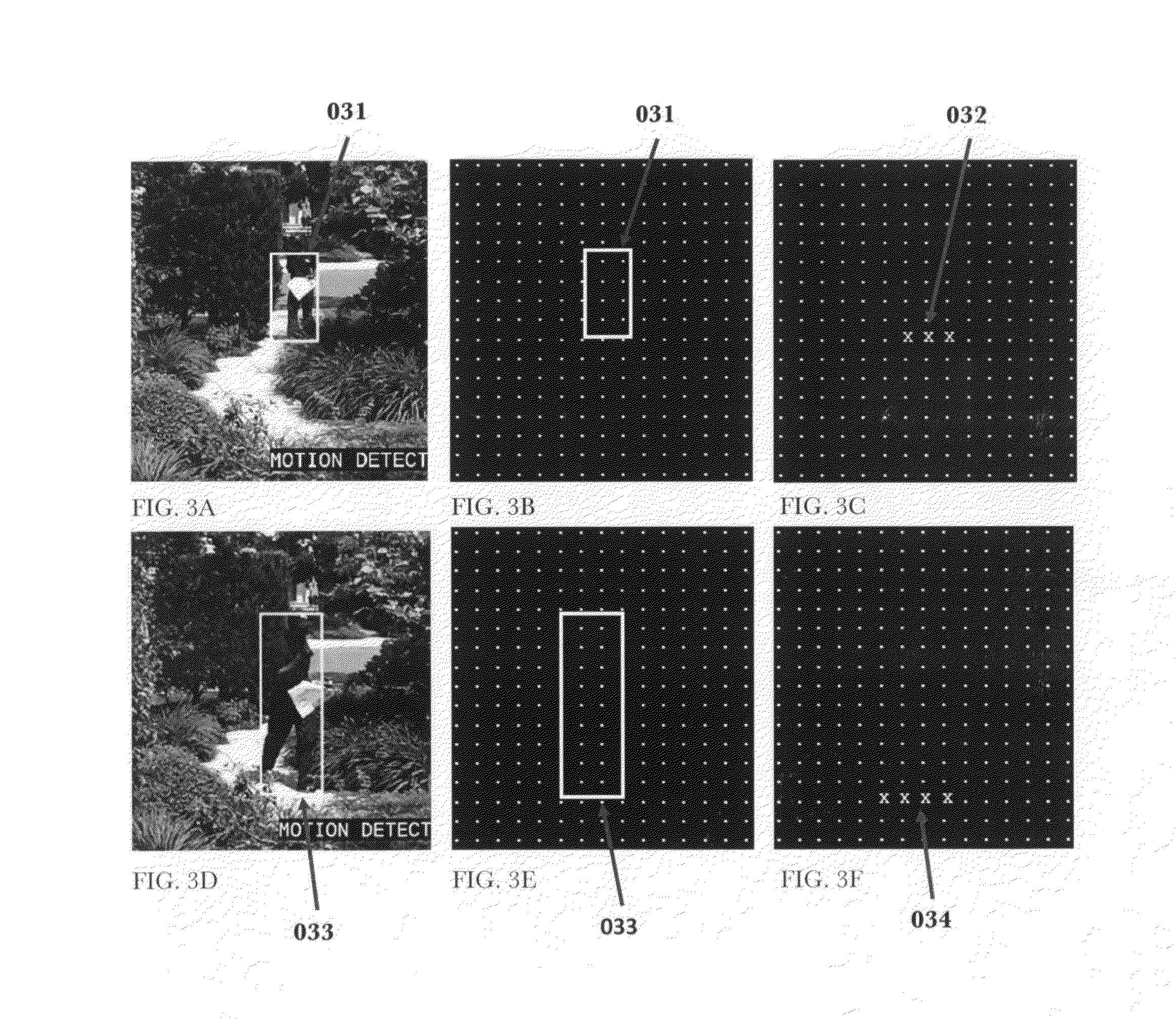
[0049]The present invention makes use of a video camera, which generally is any device with a lens and photo sensor array or similar that can capture and transmit a video signal or stream of picture images.

[0050]For the purpose for this invention, a video analytics processor is specialized software that may also include specialized hardware, designed to analyze sequential frames in a video stream and quantify changes in the image from video frame to video frame. In a preferred embodiment of this invention, this processing is performed using specialized software running on a video Digital Signal Processor or DSP semiconductor integrated in to the camera. In alternate embodiments, video analytics processing may be carried out on a general computing platform or DSP processor in the camera, computing platform or DSP processor separate from the camera, computing platform or DSP processor in a cloud computing service, on an app or software program r...


PUM


Abstract

This invention describes a method and apparatus for security monitoring with a video camera. A mathematical model consisting of an array of cells, or learning map, is used to describe the motion of any object(s) detected by the camera. When an object(s) is detected, its positional location(s) for a period of time, or motion event, is recorded in a learning map. This learning map is then compared to a reference learning map where the camera determines whether to alert the user or not that an object of interest was detected. After viewing the video of the motion event, the user provides feedback that impacts how the reference learning map is updated by information in the motion event learning map. Through this user feedback mechanism, the camera learns to more accurately determine whether or not to alert the user about future motion events, thus reducing the number of false alarms.

Description

CROSS-REFERENCE TO RELATED APPLICATIONS[0001]Provisional patent: Video Motion Detection Method and Alert Management Filed: 2014 Jun. 13, EFS ID: 19296984, Application No. 62 / 011,676STATEMENT REGARDING FEDERALLY SPONSORED RESEARCH OR DEVELOPMENT[0002]Not ApplicableREFERENCE TO SEQUENCE LISTING, A TABLE, OR A COMPUTER PROGRAM LISTING COMPACT DISK APPENDIX[0003]Not ApplicableFIELD OF THE INVENTION[0004]The present invention relates to the field of video monitoring. More particularly, the present invention relates to a method and apparatus of motion detection analysis and method of alerting users. More particularly, the present invention relates to a learning methodology whereby a user observing a detected motion instructs the system on how to respond to similar detected motions in the future.BACKGROUND OF THE INVENTION[0005]Electronic security systems date back to the 1850s where electrical switches mounted on doors and windows were wired to a remote electromechanical buzzer. A number ...

Claims


Application Information

Patent Timeline
Patent Type & Authority Applications(United States)
IPC IPC(8): G08B13/196G06K9/00G06T7/20H04N5/232
CPCG08B13/19604H04N5/23229G06T2207/30232G06T7/20G06T2207/10016G06K9/00771G08B13/19615G06V40/20G06V20/52G06V10/7784H04N23/64H04N23/6811H04N23/683G06F18/2178
Inventor HOGG, WILLIAM DAYLESFORDGUTJAHR, TROY ALLAN
Owner HOGG WILLIAM DAYLESFORD
Why Eureka
Try Eureka