Air intake for a motorized vehicle

a technology for air intake and motor vehicles, applied in the direction of vehicles, vehicle components, mechanical apparatus, etc., can solve the problems of heavy weight and complicated production of ballistic screens, and achieve the effect of low height and weight and low signatur

Inactive Publication Date: 2003-12-16
ALVIS HAGGLUNDS
View PDF21 Cites 37 Cited by
  • Summary
  • Abstract
  • Description
  • Claims
  • Application Information

AI Technical Summary

Benefits of technology

An object of the present invention is to make available a ballistically protected and signature-secured air intake for a motorized vehicle, where the perforated armour plate has a low height and weight and also a low signature with respect to both RR and infrared. For this purpose, said air intake according to the invention is characterized in that the fresh-air duct has an airflow-deflecting wall section situated between the air intake openings in the armour plate and the heat-emitting source, which wall section is provided with at least one air bypass duct for cooling the wall section. Since the design of said wall section means that it can be kept cooled during vehicle operation, this makes it difficult to detect by infrared cameras, and at the same time the perforation openings in the plate can be punched out easily as straight small holes in a relatively thin-walled armour plate with a thickness of only about 5 to 10 mm.

Problems solved by technology

Such ballistic screens are very heavy and complicated to produce.

Method used


Image

  • Air intake for a motorized vehicle
  • Air intake for a motorized vehicle
  • Air intake for a motorized vehicle

Examples


Embodiment Construction

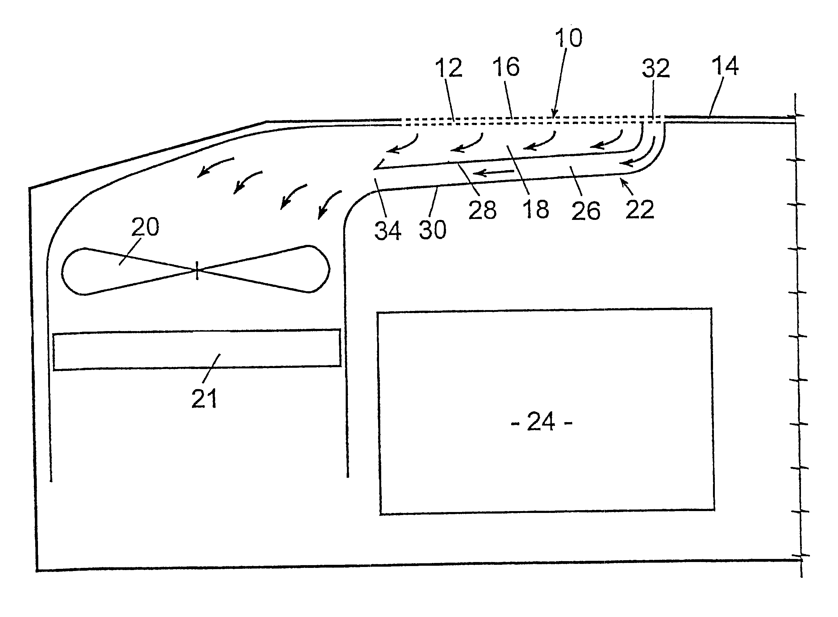
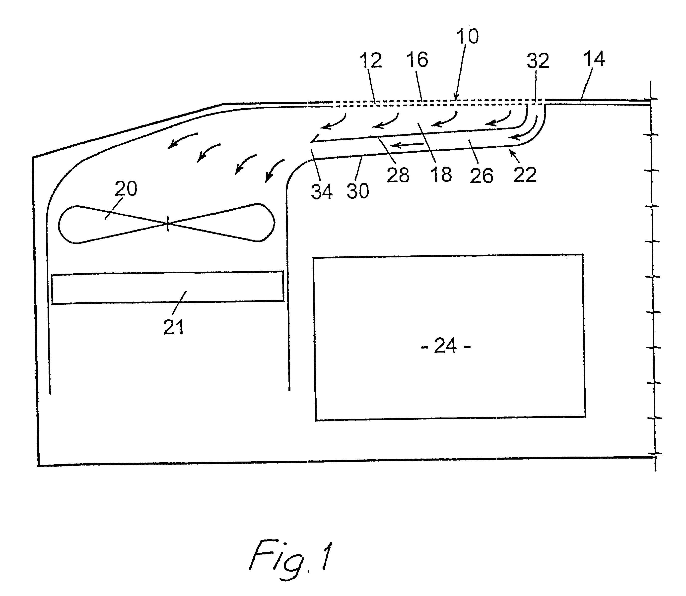
In FIG. 1, a ballistically protected fresh-air intake according to the invention for a motorized combat vehicle is designated in general by reference number 10. The air intake comprises a plane perforated armour plate 12 lying level with an outer, preferably upper bodywork plate 14 of the vehicle. The armour plate 12 has a thickness of about 5 to 10 mm, which permits simple punching out of air intake openings 16 with a diameter of the same order of size as the thickness of the plate 12.

Adjoining the inside of the perforated plate 12 is a fresh-air duct 18 in which a fan 20 (shown diagrammatically) can draw fresh air into the vehicle in order to provide the vehicle with air for the combustion of the fuel and for cooling of the engine (cooler 21) and possibly supply air to the crew areas. The duct 18 is angled immediately inside the perforated armour plate 12 by means of a wall section 22 which is situated between the plate 12 and a heat-emitting source, in this case a combustion engi...


PUM


Abstract

An air intake for a motorized vehicle, for obtaining a low radar and IR signature of a ballistically protected air intake (10) of the vehicle. The air intake (10) has a perforated armour plate (12) lying level with an outer bodywork plate (14) of the vehicle, and a fresh-air duct (18) which adjoins the inside of the perforated armour plate (12) and which has a fan (20) for sucking the fresh air necessary for running the vehicle into the duct via air intake openings (16) in the armour plate. A wall section (22) of the fresh-air duct (18) situated between the air intake openings (16) and a heat-generating source (24) in the vehicle is air-cooled.

Description

The present invention relates to an air intake for a motorized vehicle, in particular for obtaining a low radar and infrared ("IR") signature of a ballistically protected air intake of the vehicle, where a heat-emitting source in the vehicle is placed in immediate proximity to the air intake, comprising a perforated armour plate lying level with an outer bodywork plate of the vehicle, and a fresh-air duct which adjoins the inside of the perforated armour plate and which has a fan for sucking the fresh air necessary for running the vehicle into the duct via air intake openings in the armour plate.PRIOR ARTIn a combat vehicle driven by a combustion engine, in order to protect an air intake ballistically and at the same time to obtain a signature adjustment of same with respect to infrared, i.e. to give the air intake a low infrared signature, the air intake has previously been designed as an approximately 7-cm thick screen consisting of labyrinthine profiles which form air intake open...

Claims


Application Information

Patent Timeline
Patent Type & Authority Patents(United States)
IPC IPC(8): B60K13/00B60K11/00B60K11/08B60K13/02
CPCB60K11/08B60K13/02B60Y2200/24
Inventor FALK, ALFONSGUSTAFSSON, TOREOLSSON, ORJAN
Owner ALVIS HAGGLUNDS
Why Eureka
Try Eureka