Methods and apparatuses for using mobile GPS receivers to synchronize basestations in cellular networks

a mobile gps receiver and cellular network technology, applied in the field of methods, can solve the problems of not being able to perform accurate round trip timing measurements at all, not being able to perform round trip measurements to each of two or three basestations, and construction of new special fixed equipment, so as to avoid the high cost of real estate

Inactive Publication Date: 2003-12-16
SNAPTRACK
View PDF6 Cites 216 Cited by
  • Summary
  • Abstract
  • Description
  • Claims
  • Application Information

AI Technical Summary

Benefits of technology

The present invention provides various methods and apparatuses for synchronizing cellular basestations in a cellular network. One exemplary method performs time synchronization between at least two basestations, a first basestation and a second basestation, of a cellular communication system. In this exemplary method, a first time-of-day and a first location of a first mobile cellular station (MS) are determined from a first satellite positioning system (SPS) receiver which is co-located with the first mobile station (MS), and the first time-of-day and first location are transmitted by the first MS to a first basestation which determines a time-of-day of the first basestation from the first time-of-day and first location and from a known location of the first

Problems solved by technology

In other situations, it is not possible to perform round trip measurements to each of two or three basestations, but only to one basestation which is the primary one communicating with the mobile.
Or, it may not be possible to perform accurate round trip timing measurements at all due to equipment

Method used


Image

  • Methods and apparatuses for using mobile GPS receivers to synchronize basestations in cellular networks
  • Methods and apparatuses for using mobile GPS receivers to synchronize basestations in cellular networks
  • Methods and apparatuses for using mobile GPS receivers to synchronize basestations in cellular networks

Examples


Embodiment Construction

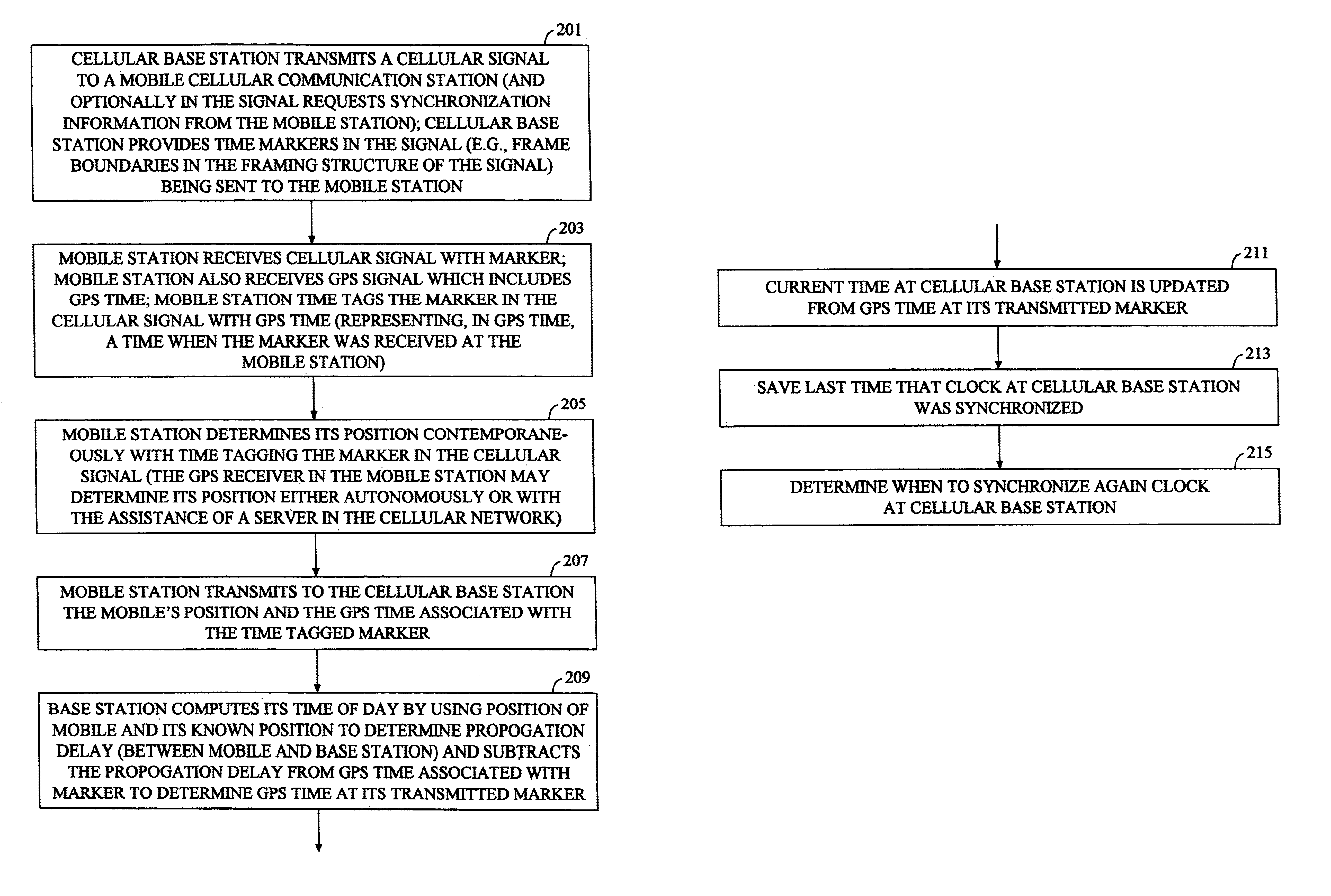
Various methods and apparatuses for determining time at a cellular basestation and for otherwise synchronizing cellular basestations in a cellular network are described herein. In the following description, numerous specific details are set forth in order to provide a thorough understanding of the present invention. For example, various architectures for basestations and mobile communication stations are provided for illustrative purposes rather than to be construed as limitations of the present invention. It will be evident, however, to one skilled in the art that the present invention may be practiced without these specific details. In other instances, well-known structures and devices are shown in block diagram form to facilitate explanation.

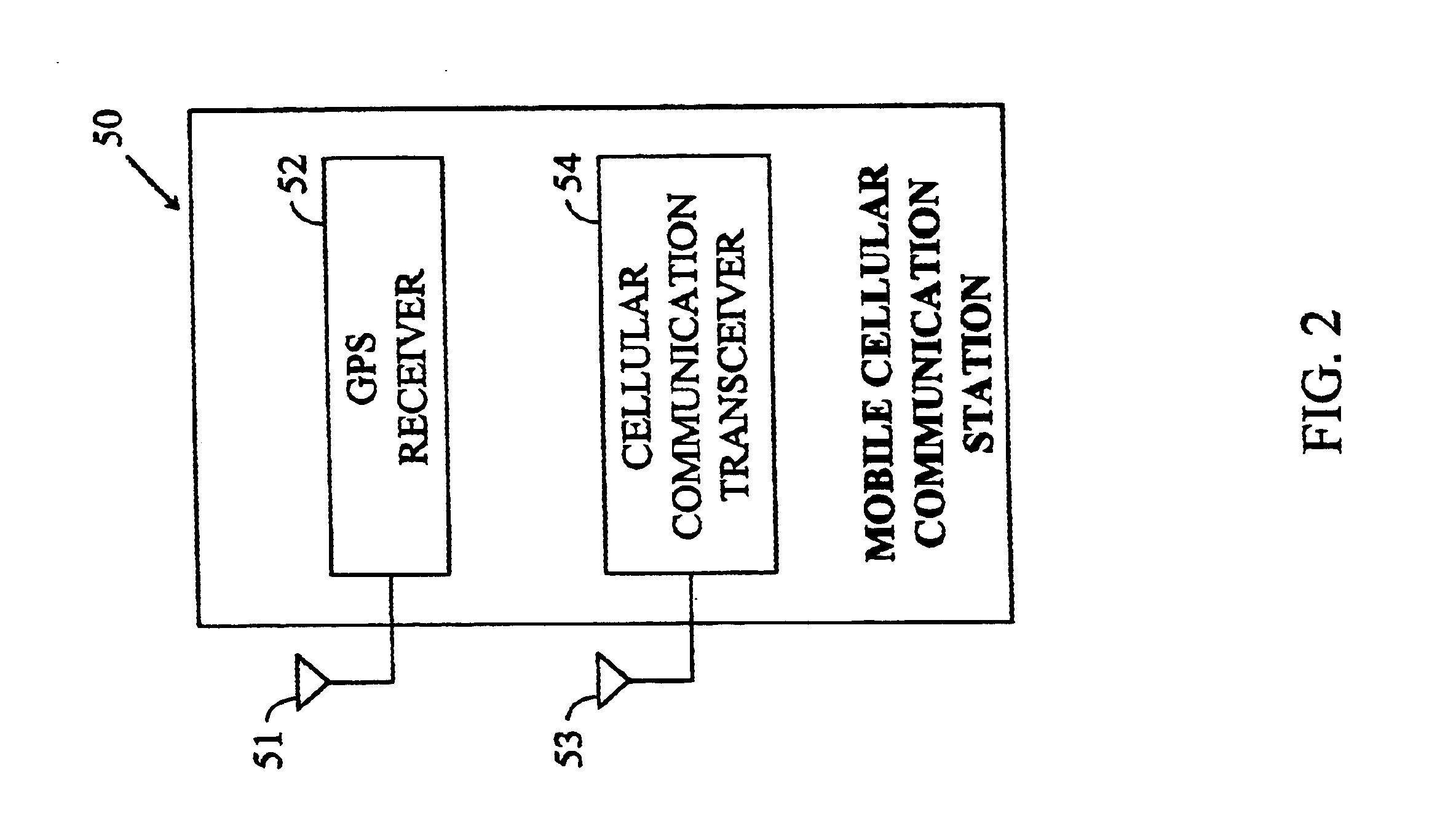
In one approach described herein, mobile communication stations are utilized that contain (or are coupled to) GPS receivers which determine both time-of-day and position. FIG. 2 shows an example of such a mobile communication station. This GP...


PUM


Abstract

Methods and apparatuses for synchronizing basestations in a cellular network. One exemplary method performs time synchronization between at least two basestations, a first basestation and a second basestation, of a cellular communication system. In this exemplary method, a first time-of-day and a first geographical location of a first mobile cellular receiver station (MS) are determined from a first satellite positioning system (SPS) receiver which is co-located with the first MS, and the first time-of-day and first location are transmitted by the first MS to a first basestation which determines a time-of-day of the first basestation from the first time-of-day and first location and from a known location of the first basestation. Also in this exemplary method, a second time-of-day and a second geographical location of a second MS are determined from a second SPS receiver which is co-located with the second MS, and the second time-of-day and the second location are transmitted to a second basestation which determines a time-of-day of the second basestation from the second time-of-day and the second location and a known location of the second basestation. Other methods and apparatuses are also described for synchronizing basestations in a cellular network.

Description

BACKGROUND OF THE INVENTIONThe present invention relates to the field of cellular communication systems, and particularly those systems where the location of a mobile cellular communication station (MS) is determined.In order to perform position location in cellular networks (e.g. a cellular telephone network) several approaches have been utilized which perform triangulation based upon the use of timing information sent between each of several basestations and a mobile device, such as a cellular telephone. In one approach, called Time Difference of Arrival (TDOA), the times of reception of a signal from a mobile is measured at several basestations, and these times are transmitted to a location determination entity, called a location server, which computes the position of the mobile. For this approach to work, the times-of-day at the various basestations need to be coordinated to provide accurate location. Also, the position of the basestations needs to be known accurately. FIG. 1 sh...

Claims


Application Information

Patent Timeline
IPC IPC(8): G01S19/05H04B7/26H04W4/02H04W4/029H04W56/00
CPCG01S11/08H04B7/2693H04W56/00H04L69/28H04W4/02H04W4/029
Inventor KRASNER, NORMAN F.JOLLEY, EDWARD V.
Owner SNAPTRACK
Why Eureka
Try Eureka