

Seat occupant restraint system for vehicle
a seat occupant and seat belt technology, applied in the direction of pedestrian/occupant safety arrangement, instruments, tractors, etc., can solve the problems of rear end collision out of consideration, seat belt system merely takes up a slack, etc., and achieve the effect of effectively restrainting the seat occupan
- Summary
- Abstract
- Description
- Claims
- Application Information
AI Technical Summary
Benefits of technology
Problems solved by technology
Method used
Image

Examples
first embodiment
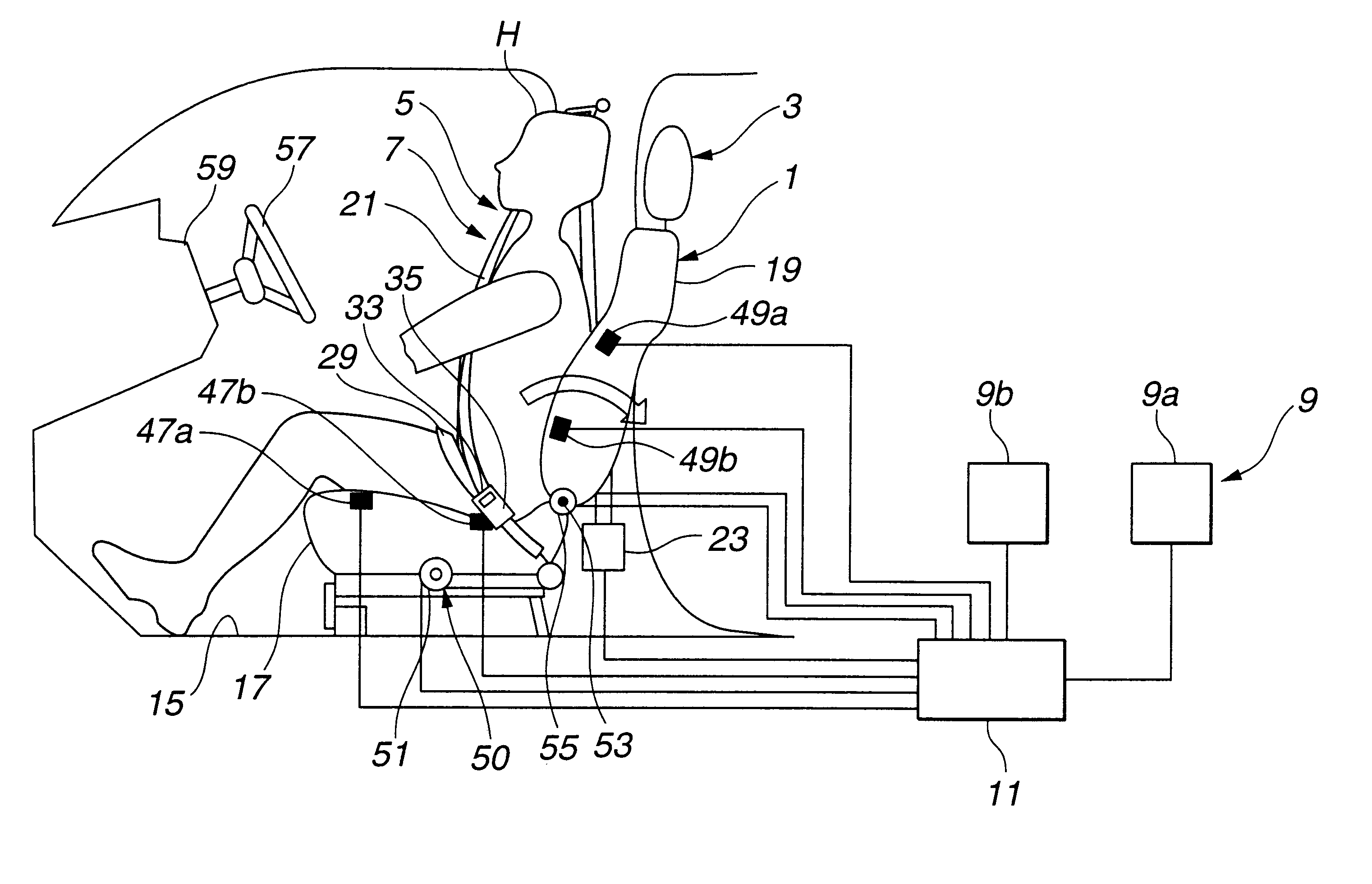
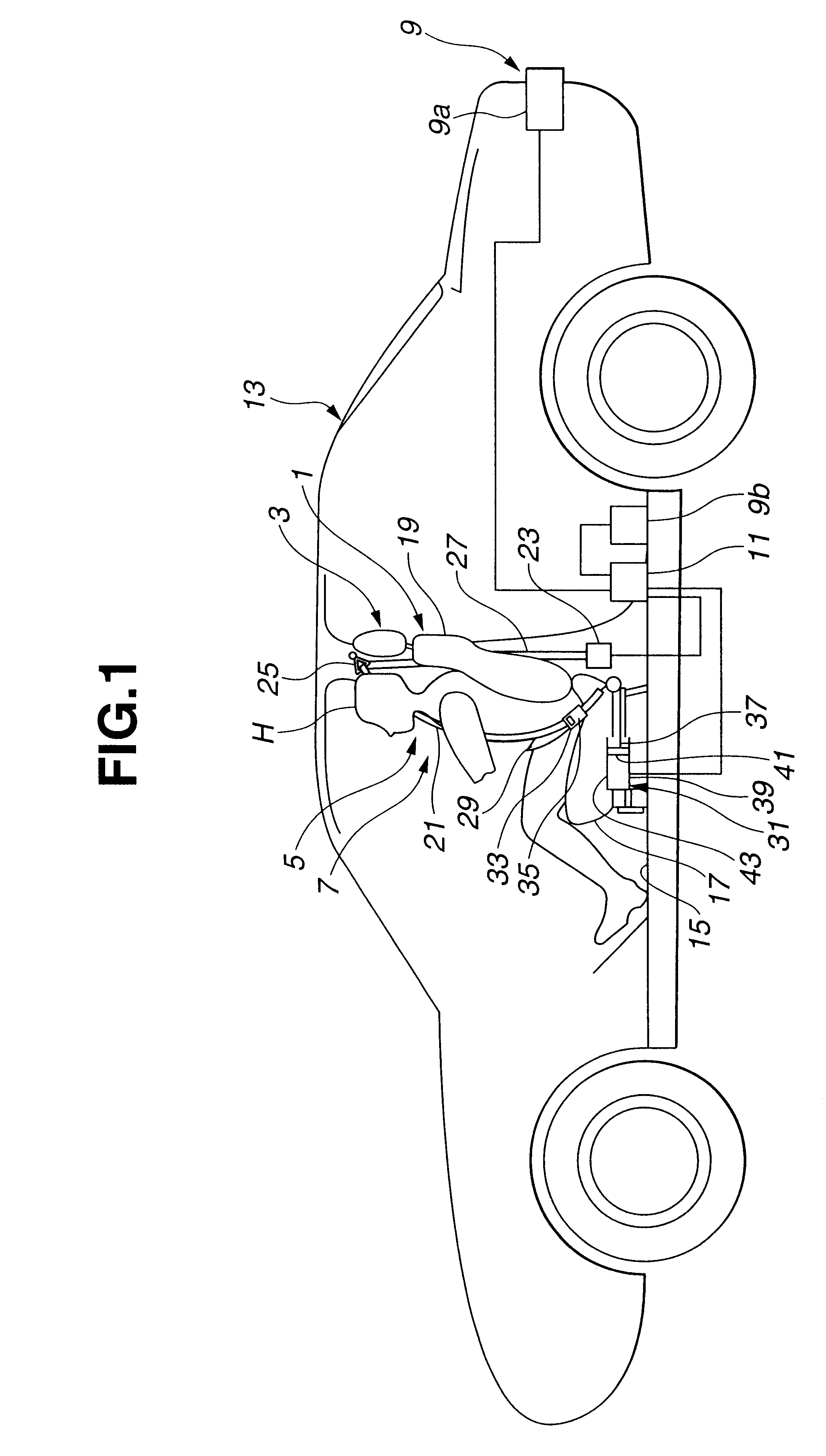
FIG. 1 shows a vehicle equipped with a seat occupant restraint system according to the present invention. The vehicle includes at least one seat 1, a headrest 3 mounted on seat 1, a restraining or restrain system, such as a seat belt system, including at least a first restraint section 5 for restraining the head of a seat occupant toward headrest 3 and a second restraint section 7 for correcting the posture of the seat occupant, a rear end collision sensor 9 and a controller 11.
Seat 1 is mounted on a floor 15 of a vehicle body 13. Seat 1 includes at least a seat cushion 17 and a seat back 19. Headrest 3 is mounted on the top of seat back 19, and designed to support the head of a seat occupant seated on seat 1 from the back side of the head. Headrest 3 of this example is of an adjustable type capable of adjusting the vertical position of headrest 3 with respect to seat back 19.
Restrain system of this example includes an upper torso restraint in the form of a shoulder belt 21 and a fi...
second embodiment
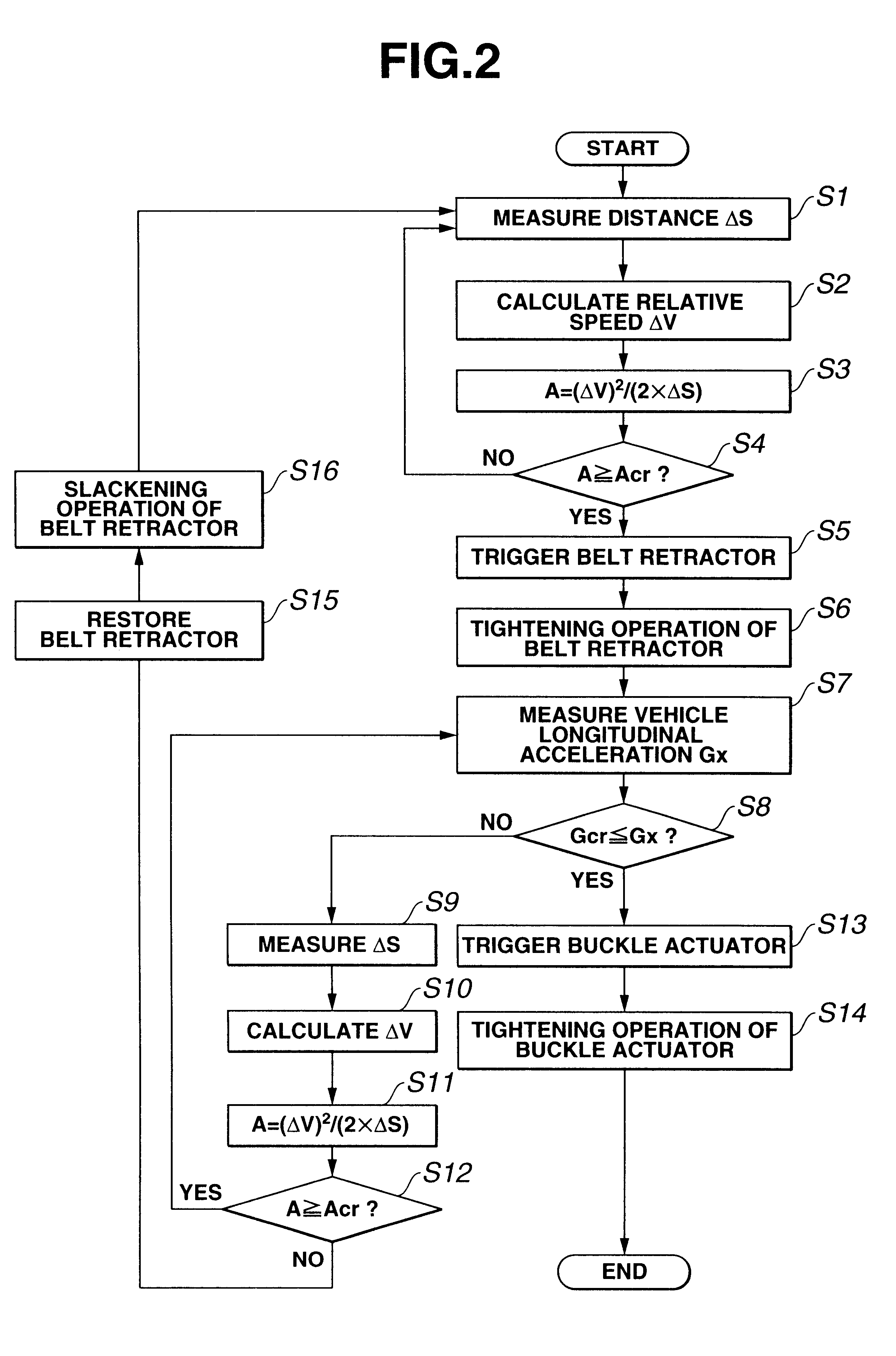
FIG. 8 shows a restraint control procedure according to the Steps S1.about.S4 and S7.about.Sl4 are substantially identical to corresponding steps S1.about.S4 and S7.about.S14 shown in FIG. 2. In FIG. 8, steps S25.about.S28 are added after step S4, steps S5 and S6 are interposed between step S26 and S7, and steps S15 and S16 are replaced by similar steps S21 and S22. Steps S25 and 26 constitute a section to check the posture of a seat occupant.
At step S25 following step S4, controller 11 obtains a seat cushion front load Fcf sensed by front load sensing unit 47a, a seat cushion rear load Fcr sensed by rear load sensing unit 47b, a seat back upper load Fbu sensed by upper load sensing unit 49a and a seat back lower load Fbl sensed by lower load sensing unit 49b.
At step S26, controller 11 compares front and rear seat cushion loads Fcf and Fcr with each other and compares seat back upper and lower loads Fbu and FbI with each other, and judges that the seat occupant is not in a standard...
third embodiment
FIG. 13 shows a restraint control procedure according to the Steps S33.about.S36 are interposed between step S25 and S26. In the other points, FIG. 13 is substantially identical to FIG. 8.
Step S33 is a step to measure the seat back angle of seat back 19. The actual seat back angle .alpha.' is determined from the signal from seat back angle sensor 53. Step S34 compares the sensed actual seat back angle .alpha.' with a reference angle a stored in a memory section in controller 11. When the sensed actual seat back angle .alpha.' is equal to or greater than the reference angle .alpha. (.alpha..ltoreq..alpha.'), controller 11 considers that seat back 19 is reclined backward beyond the reference, and proceeds from step S34 to step S35 to produce an actuation signal to command a forward rotation of seat back 19 to raise seat back 19. In response to this actuation signal, electric seat reclining mechanism 55 rotates seat back 19 forward and raises seat back 19 to the reference angle a at s...
PUM
 Abstract
Description
Claims
Application Information