

Ink jet recording head and method of producing a plate member for an ink jet recording head
a technology plate member, which is applied in the field of ink jet recording head, can solve the problems of flexural deformation of the member and shrinkage of polymer materials, and achieve the effect of suppressing the deformation of the plate member during the production process and simplifying the production process
- Summary
- Abstract
- Description
- Claims
- Application Information
AI Technical Summary
Benefits of technology
Problems solved by technology
Method used
Image

Examples
Embodiment Construction
Hereinafter, the invention will be described in detail with reference to illustrated embodiments.
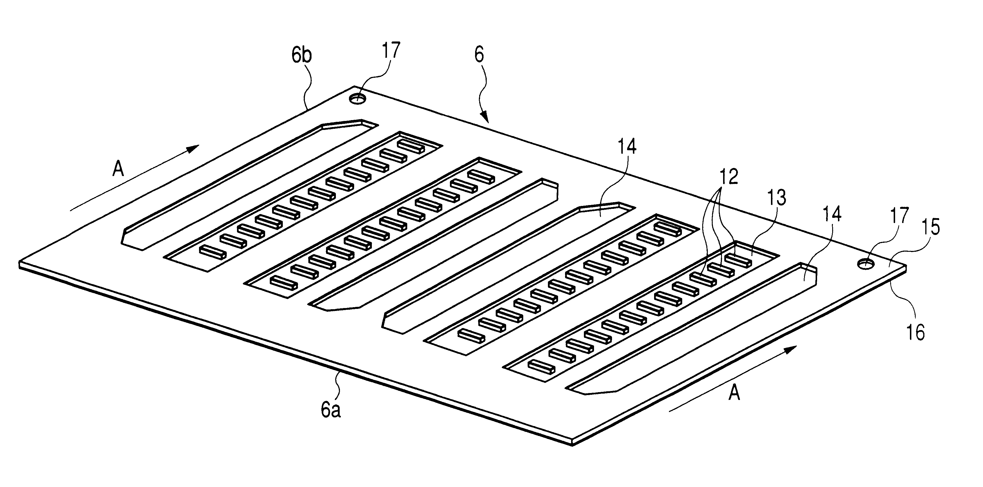
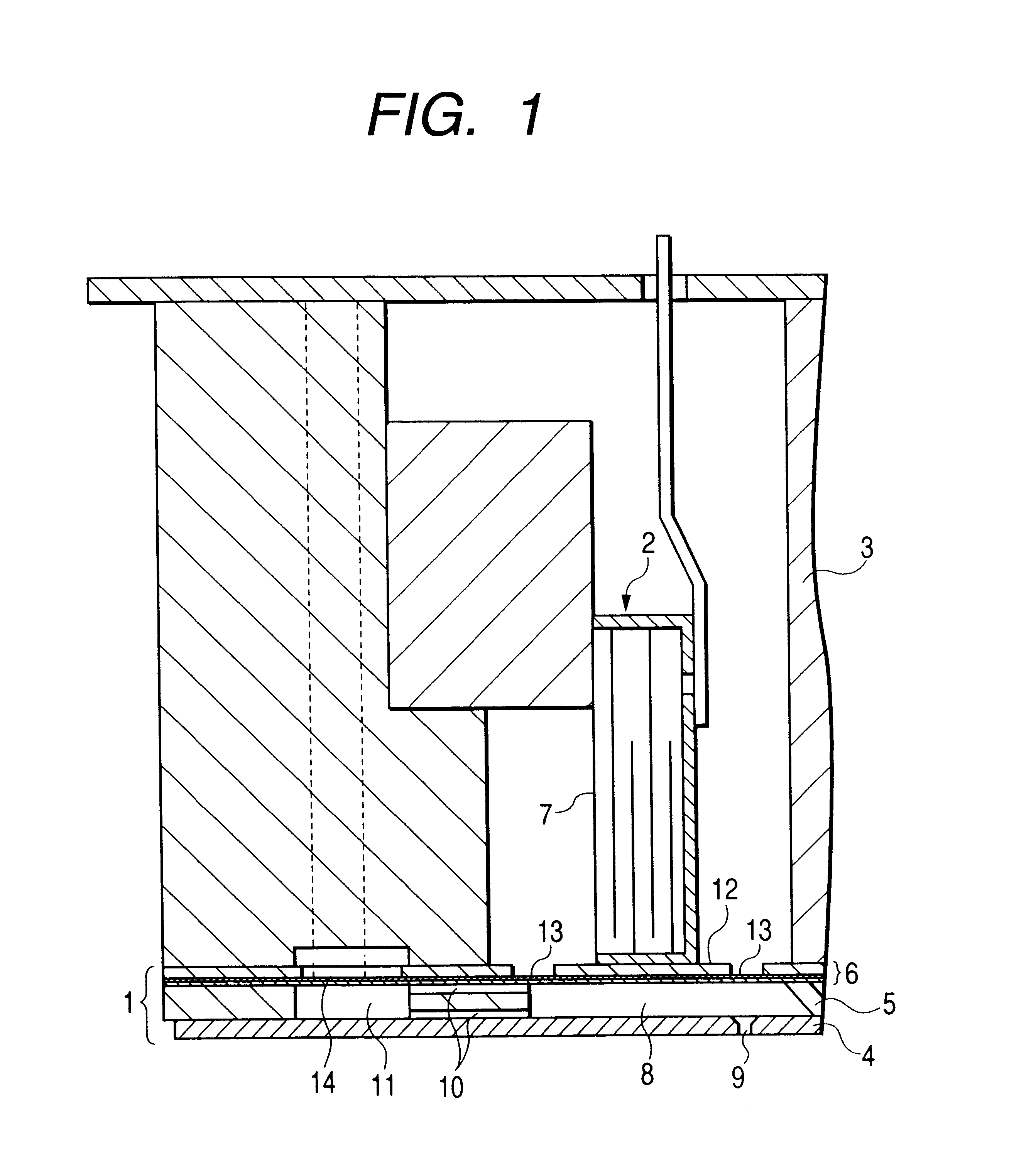
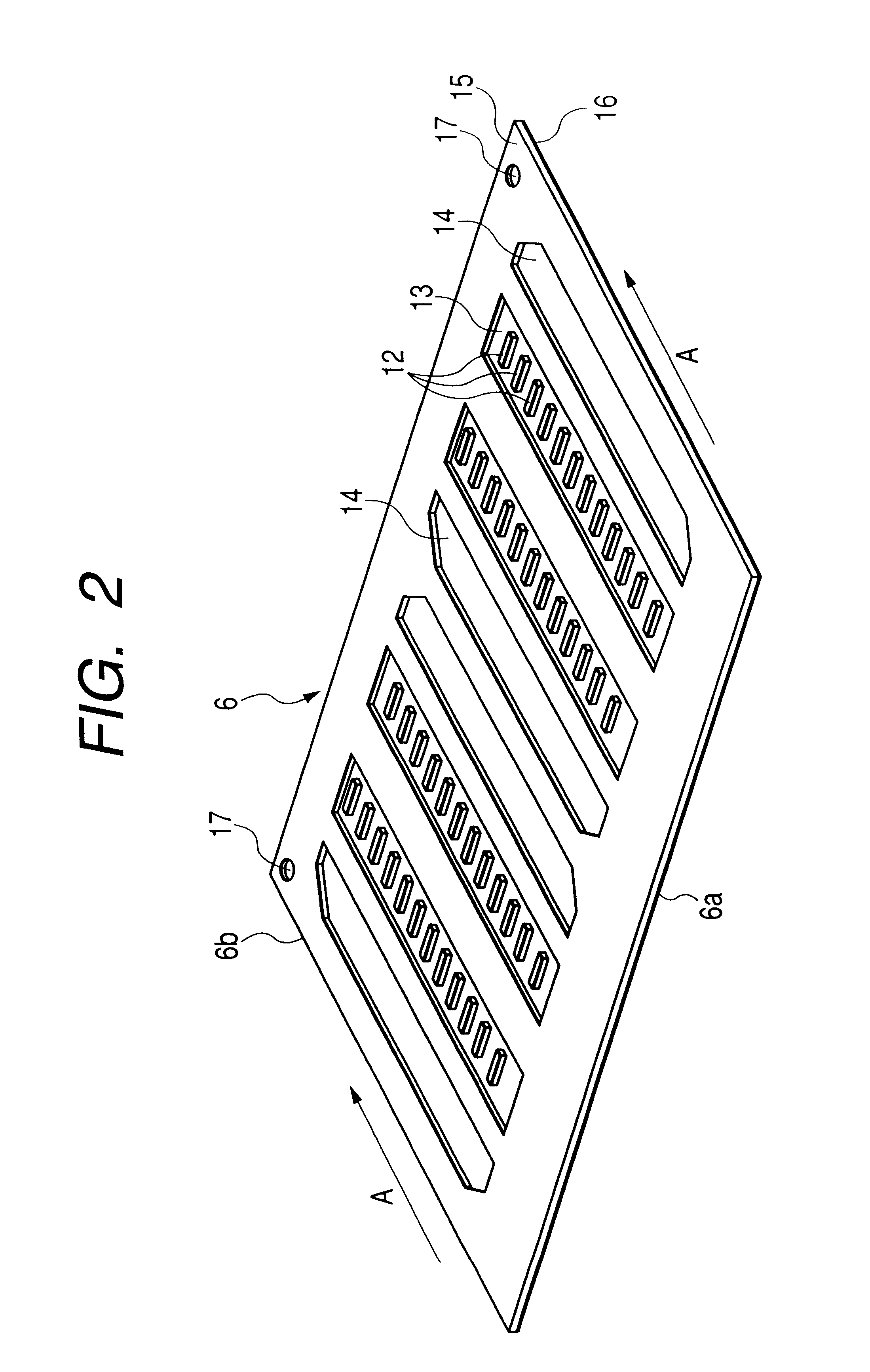
FIG. 1 shows an embodiment of the ink jet recording head of the invention. The ink jet recording head is configured by integrally fixing a channel unit 1 and a piezoelectric vibrator unit 2 via a head holder 3. The channel unit 1 is configured by laminating a nozzle plate 4, a channel forming substrate 5, and a plate member 6. Pressure generating chambers 8 are contracted and expanded by expansion and contraction of respective piezoelectric vibrators 7 of the piezoelectric vibrator unit 2, thereby ejecting ink droplets.
The nozzle plate 4 is formed with nozzle openings 9 which respectively communicate with the pressure generating chambers 8, and the channel forming substrate 5 is formed with the pressure generating chambers 8, ink supply ports 10, and reservoirs 11. In this embodiment, a common reservoir 11 is provided for each row of the pressure generating chambers 8, and ink supply por...
PUM
| Property | Measurement | Unit |
|---|---|---|
| thickness | aaaaa | aaaaa |
| temperature | aaaaa | aaaaa |
| ink resistance | aaaaa | aaaaa |
Abstract
Description
Claims
Application Information