
System and method for a software controlled cache

Inactive Publication Date: 2003-12-23
ORACLE INT CORP
View PDF26 Cites 33 Cited by
  • Summary
  • Abstract
  • Description
  • Claims
  • Application Information

AI Technical Summary

Benefits of technology

The present invention overcomes the disadvantages of the prior art by providing a cache memory system and method for operating the same that realizes improved handling of data by providing predictable access times, reduced cache-misses and reduction of cache-conflicts.
The advantages of the present invention include: (i) predictable access times, (ii) reduced cache-misses, (iii) the reduction or elimination of cache conflicts and (iv) direct program control of what data is in certain portion of the cache.

Problems solved by technology

Thus, the processor is often forced to wait for the memory system to respond.
This scheme, while simple, can result in a cache-conflict or thrashing in which a sequence of accesses to memory repeatedly overwrites the same cache entry, resulting in a cache-miss on every access.
However, one problem with fully associative caches is that the whole main-memory address must be used as a tag, thereby increasing the size of the tag-field and reducing cache capacity for storing data.
While a significant improvement over cache systems without prefetching all ofthe prior art prefetching mechanisms suffer from a common short coming.
Thus, while conventional prefetching mechanisms can work well in prefetching data stored sequentially, such as in an array where elements are stored contiguously, they can actually lead to a high number of cache-misses, by displacing needed data in the cache with erroneously prefetched data, and to unpredictable access times for non-sequential, pointer-linked data structures.

Method used


Image

  • System and method for a software controlled cache
  • System and method for a software controlled cache
  • System and method for a software controlled cache

Examples


Embodiment Construction

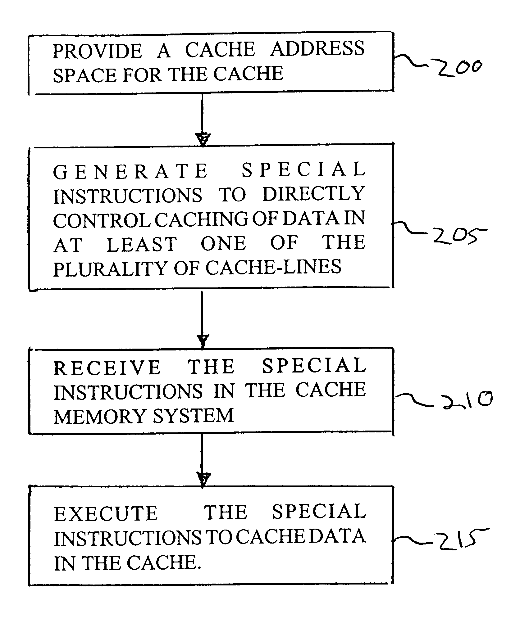
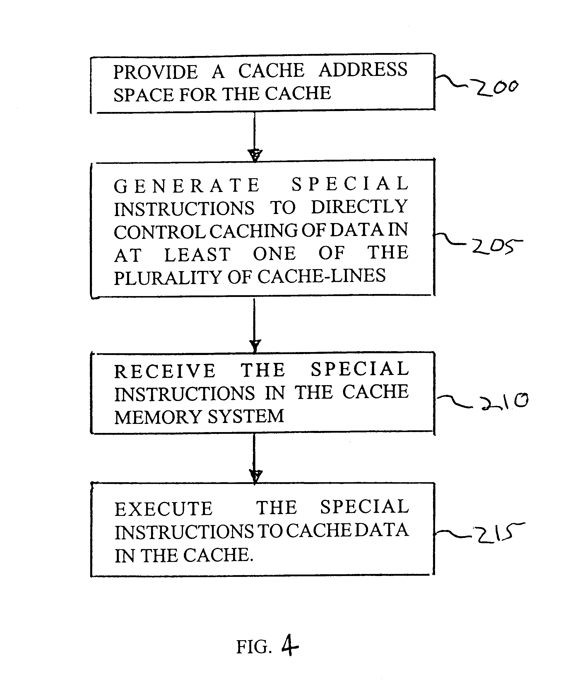
The present invention is directed to cache memory systems and methods of operating the same to provide improved handling of data in a cache memory system for caching data transferred between a processor capable of executing a program and a main-memory

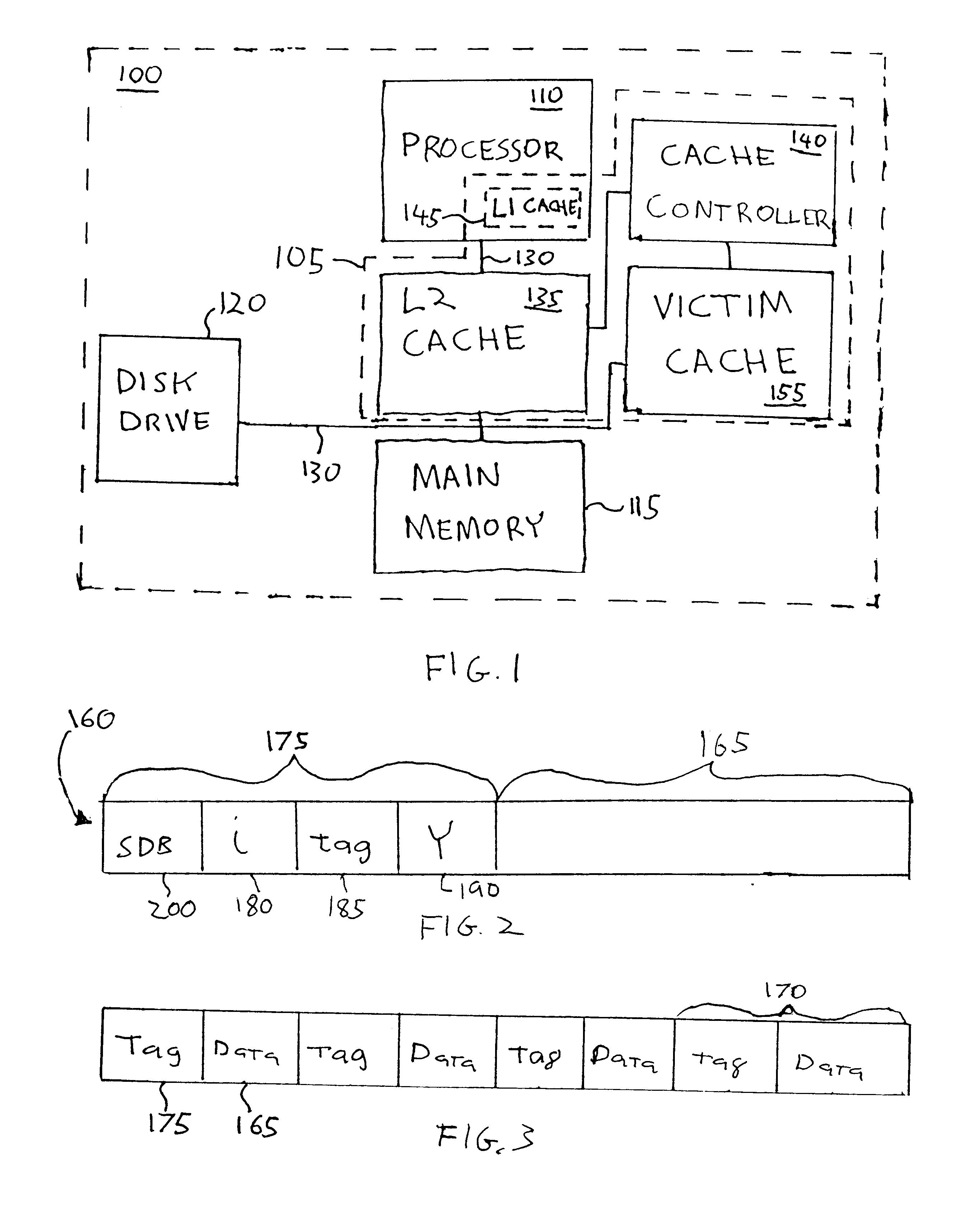
FIG. 1 shows a block diagram of an exemplary embodiment of a computer system 100 in which an embodiment of a cache memory system 105 of the present invention can be incorporated. For purposes of clarity, many ofthe details of computer systems that are widely known and are not relevant to the present invention have been omitted. In addition to cache memory system 105, computer system 100 typically includes central processing unit (CPU) or processor 110 for executing instructions for a computer application or program (not shown), main-memory 115 for storing data and instructions while running the application, a mass-data-storage device, such as disk drive 120, for a more permanent storage of data and instructions, system bus 130 coupling ...


PUM


Abstract

A system and method are provided for improved handling of data in a cache memory system (105) for caching data transferred between a processor (110) capable of executing a program and a main-memory (115). The cache memory system (105) has at least one cache (135) with several cache-lines (160) capable of caching data therein. In the method, a cache address space is provided for each cache (135) and special instructions are generated and inserted into the program to directly control caching of data in at least one ofthe cache-lines (160). Special instructions received in the cache memory system (105) are then executed to cache the data. The special instructions can be generated by a compiler during compiling of the program. Where the cache memory system (105) includes a set-associative-cache having a number of sets each with several cache-lines (160), the method can further include the step of determining which cache-line in a set to flush to main-memory (115) before caching new data to the set.

Description

FIELDThe present invention relates generally to memory systems, and more particularly to cache memory systems and a method of operating the same that provides efficient handling of data.BACKGROUNDModern computer systems generally include a central processing unit (CPU) or processor for processing data and a memory system for storing operating instructions and data. Typically, the speed at which the processor can decode and execute instructions exceeds the speed at which instructions and data can be transferred between the memory system and the processor. Thus, the processor is often forced to wait for the memory system to respond. This delay is commonly known as memory latency. To reduce, if not eliminate, this time many computer systems now include a faster memory known as a cache memory between the processor and main-memory.A cache memory reduces the memory latency period by temporarily storing a small subset of data from a lower-level memory such as a main-memory or mass-storage-...

Claims


Application Information

Patent Timeline
IPC IPC(8): G06F9/38G06F9/30
CPCG06F9/383G06F9/30101
Inventor DAMRON, PETER C.
Owner ORACLE INT CORP
Learn More