Gas fired radiant heating unit and method of operation thereof

a technology of radiant heating and gas fired heat, which is applied in the direction of heating fuel, combustion process, combustion ignition, etc., can solve the problems of ceramic fiber damage, mesh failure,

Inactive Publication Date: 2003-12-30
HEAT DESIGN EQUIP
View PDF7 Cites 27 Cited by
  • Summary
  • Abstract
  • Description
  • Claims
  • Application Information

AI Technical Summary

Problems solved by technology

However, due to the extreme temperature conditions under which the heating unit operates, the mesh can fail or the ceramic fiber can become damaged.

Method used


Image

  • Gas fired radiant heating unit and method of operation thereof
  • Gas fired radiant heating unit and method of operation thereof
  • Gas fired radiant heating unit and method of operation thereof

Examples


Embodiment Construction

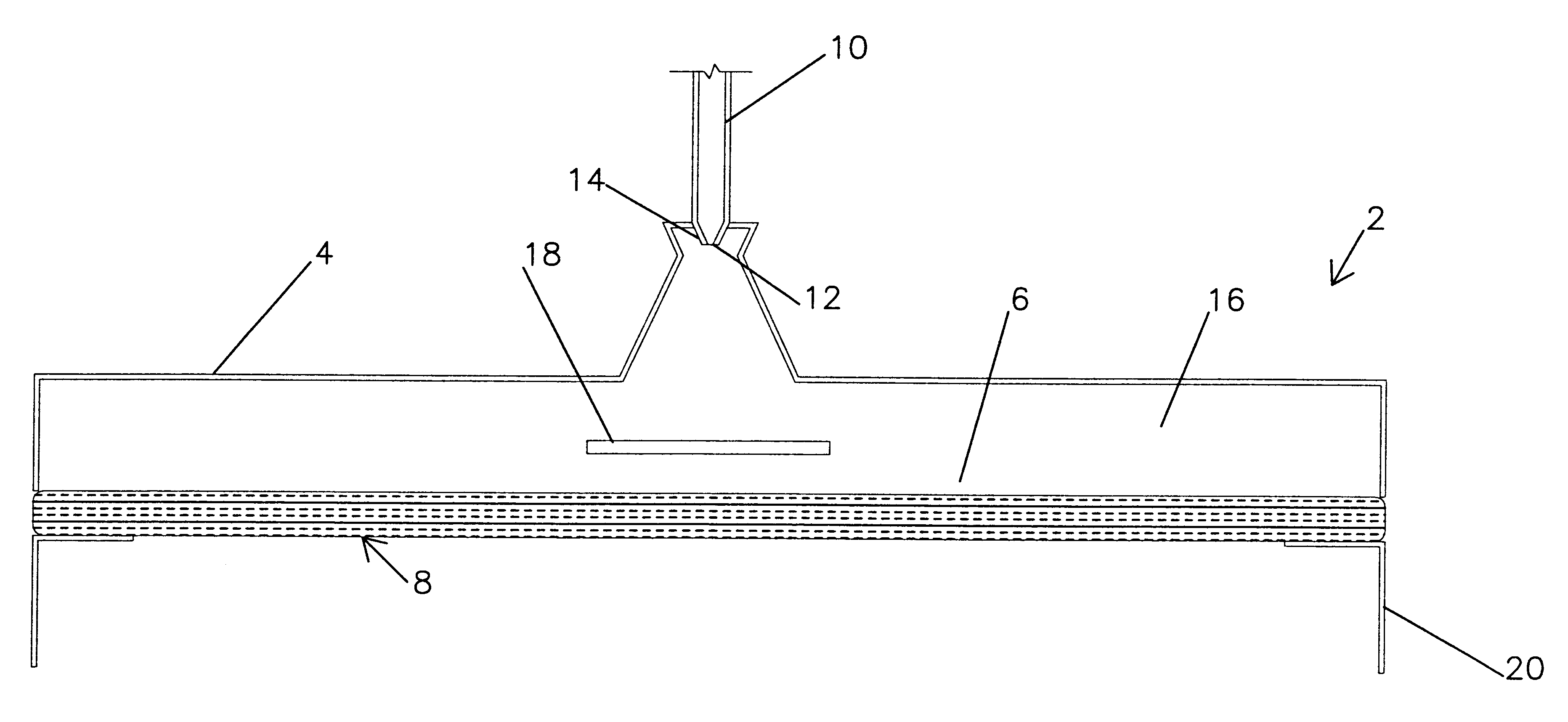
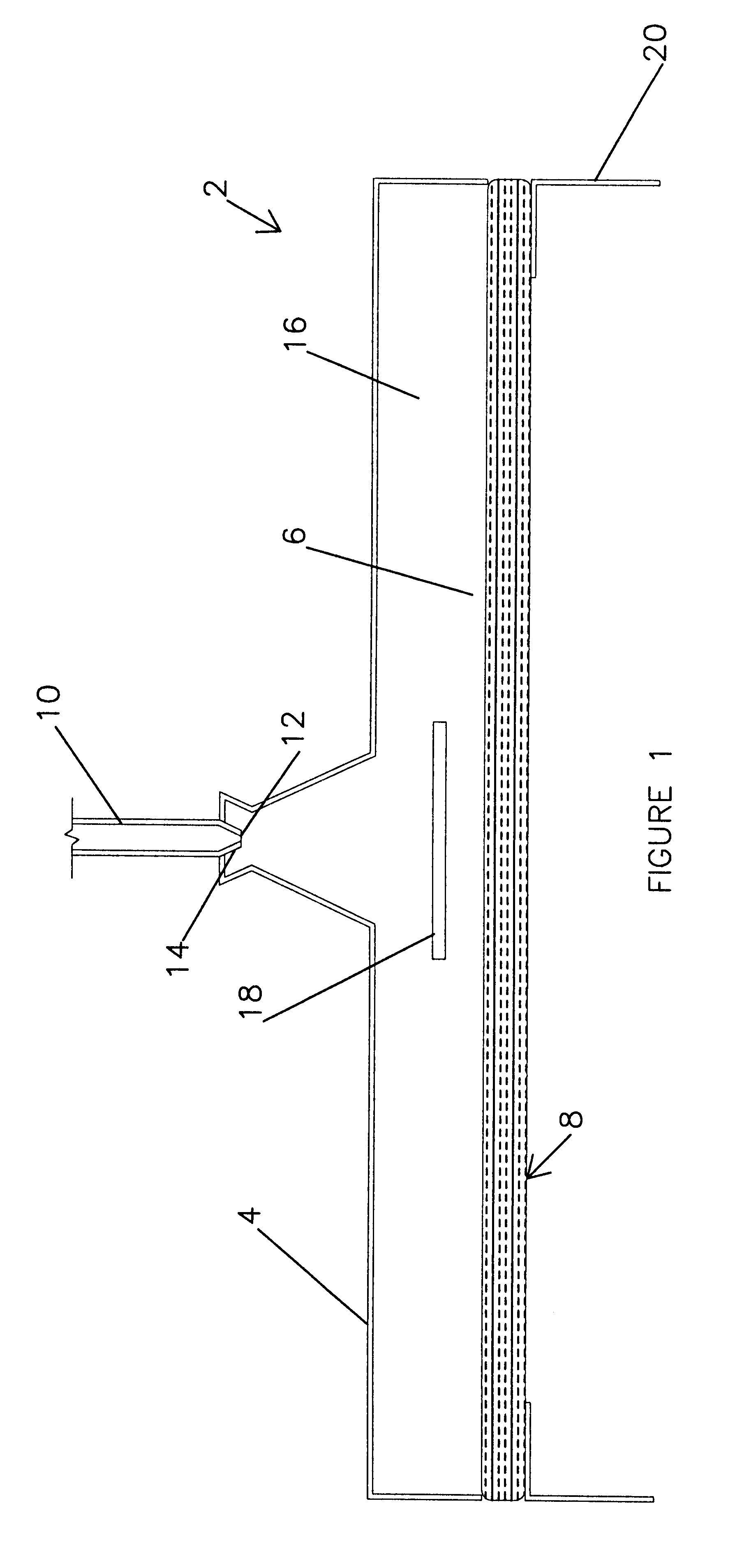
In FIG. 1, there is shown a burner 2 having a housing 4 with a bottom 6 covered by a cartridge 8. The housing can be referred to, more specifically, as a plenum. The burner 2 has a fuel supply line 10, which supplies a fuel mixture through an orifice 12 in a venturi 14. The housing 4 and cartridge 8 define a chamber 16. Within the chamber 16, there is located a deflector 18, which distributes the fuel / air mixture evenly into the cartridge 8. A skirt 20 extends downward from the cartridge 8. The skirt protects the cartridge from physical damage and maintains a minimum distance between the cartridge and a surface (not shown) to be heated. The cartridge 8 is sandwiched between the housing and the skirt.

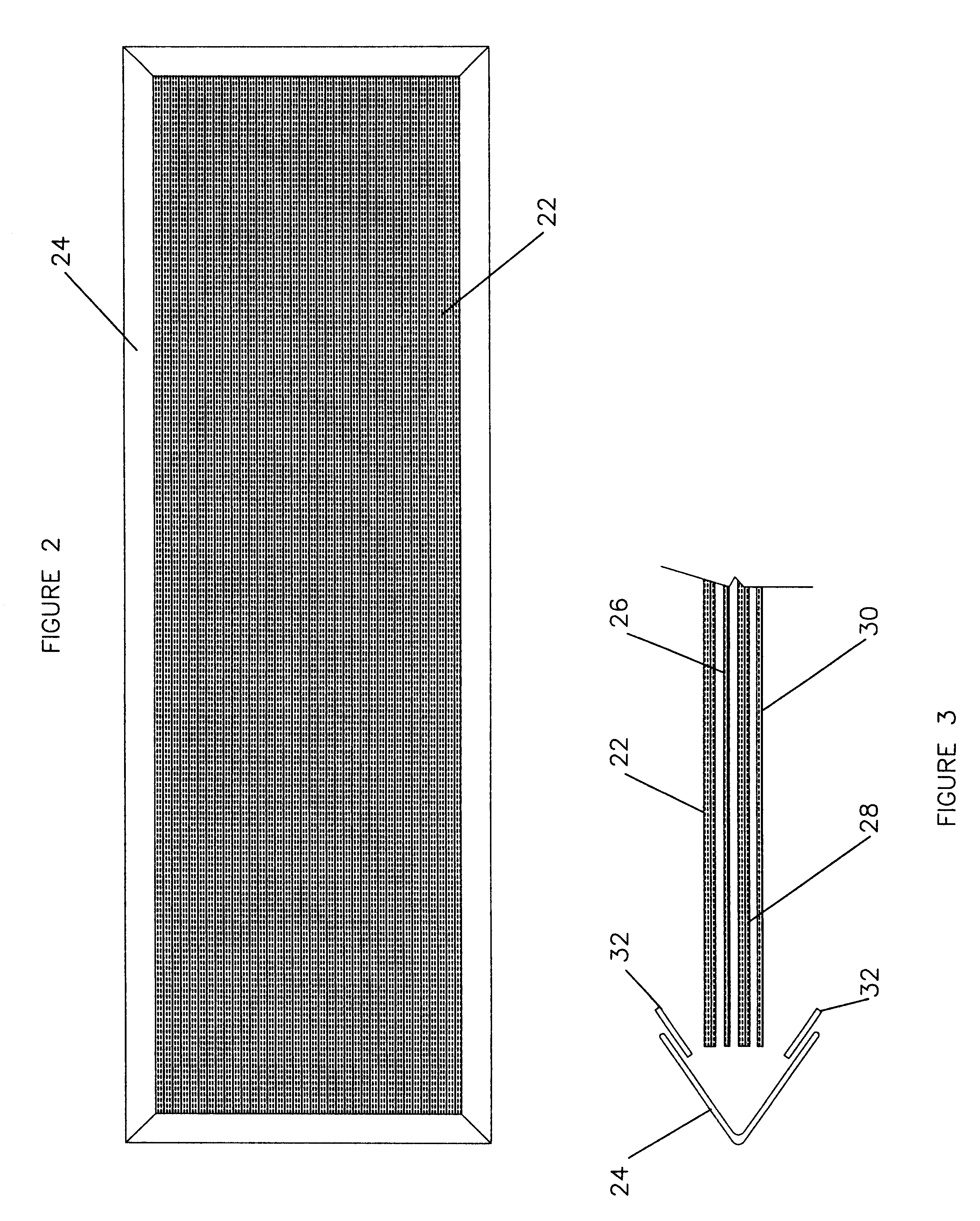
In FIG. 2, it can be seen that the cartridge has a top layer 22 and a rigid border 24.

In FIG. 3, it can be seen that the cartridge has four layers, a top layer 22 being an expandable metal screen, a second layer 26, located immediately beneath the top layer 22, made of stainless steel me...


PUM

PropertyMeasurementUnit
pressureaaaaaaaaaa
pressureaaaaaaaaaa
pressureaaaaaaaaaa

Abstract

A heating unit has a cartridge that constitutes a single component, which can be readily removed and replaced with a new cartridge. The cartridge is a plurality of non-flammable layers bound together in a border. The layers include a stainless steel mesh located above a layer of ceramic wool. With the cartridge, replacement can be accomplished in approximately fifty minutes compared to a downtime of a week or more previously.

Description

1. Field of InventionThis invention relates to an improved radiant heating unit and to an improved method of operation thereof. More particularly, this invention relates to a gas powered radiant heating unit that can be used with roadway surface reconditioning machines to heat various surfaces, including asphalt over a relatively large area.2. Description of the Prior ArtIt is known to have radiant heating units for use in repairing asphalt roadway surfaces. The units can be used with a scarifier or patcher. Most units are powered by low pressure propane gas. A radiant heating unit is described in U.S. Pat. No. 5,218,952 issued to Neufeldt on Jun. 15, 1993. The Neufeldt patent describes a radiant heating unit having a housing with a layer of ceramic fiber sandwiched between two layers of mesh. The heating unit described in the Neufeldt patent works well and is designed to withstand rough treatment. However, due to the extreme temperature conditions under which the heating unit opera...

Claims


Application Information

Patent Timeline
Patent Type & Authority Patents(United States)
IPC IPC(8): F23D14/14F23D14/12
CPCF23D14/145F23D2212/201F23D2212/103F23D2203/106
Inventor KIESWETTER, ROBERT E.
Owner HEAT DESIGN EQUIP
Why Eureka
Try Eureka