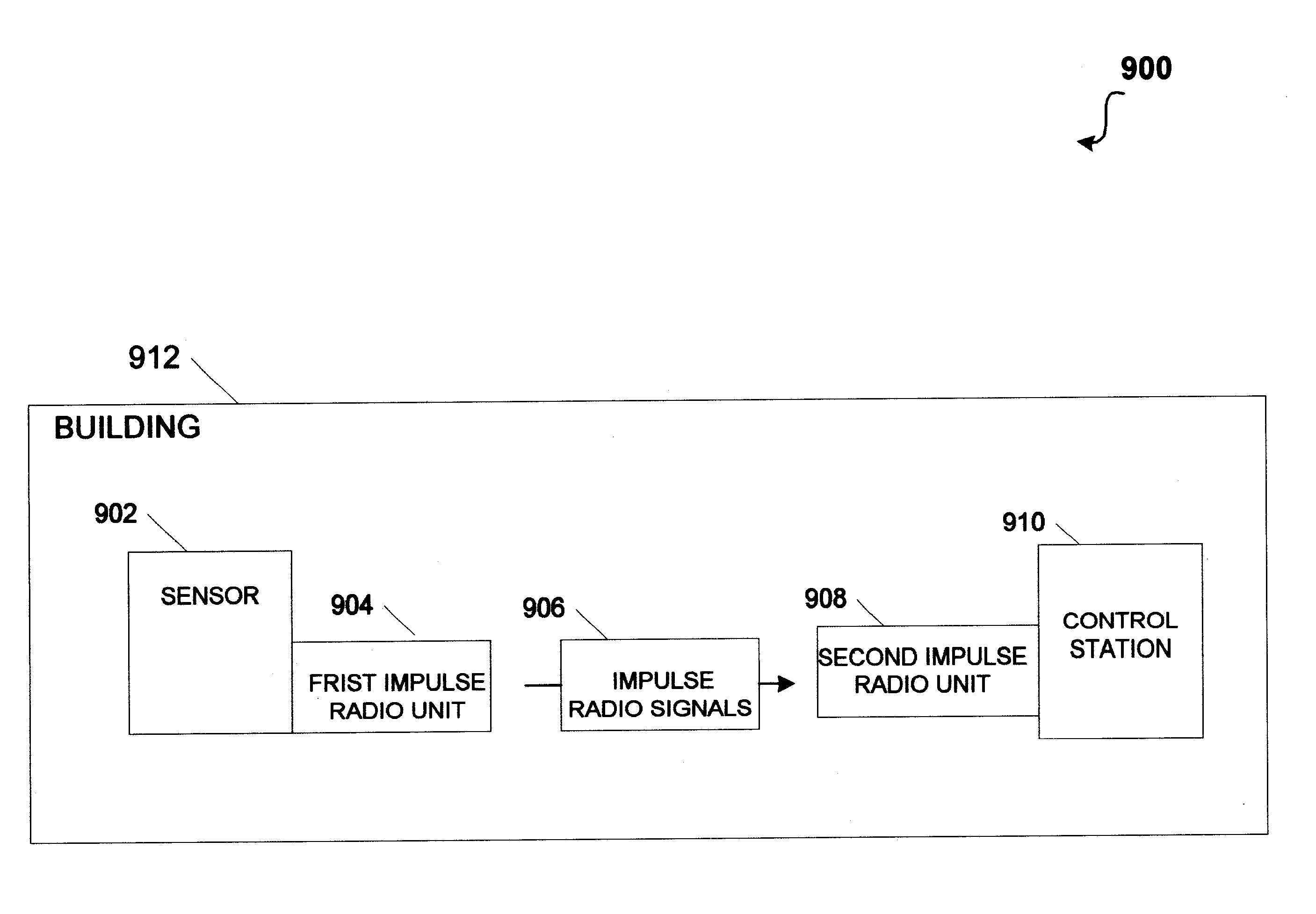
Unfortunately, to date there does not appear to be any sensor that effectively enables people to monitor and control the environment outside or within a building.
For instance, most sensors (e.g., thermostats) are hard wired to a controller (e.g., heating / cooling controller) which can be problematical in that only a few hard-wired sensors are typically used to control the environment (e.g., temperature) within the entire building.
Another problem with hard-wired sensors is that there is a large expense to install these sensors.
However, new problems have arisen with the use of
wireless sensors because with standard radio transmissions there are often problematical "dead zones" within a building that may interfere with the
wireless link between the sensor and the controller.
The "dead zones" are caused by the closed structure of the building, which can make it difficult for a sensor attached to standard radio
transmitter to maintain contact with a standard
radio receiver attached to a controller.
In particular, the standard radio signals sent from the standard radio
transmitter attached to the sensor may not be able to penetrate a certain wall or floor within the building and as such may not reach the standard
radio receiver attached to the controller.
Essentially, the standard radio
receiver may not be able to demodulate the standard
radio signal because the transmitted
radio signal effectively cancels itself out by bouncing of walls and floors of the building before reaching the standard radio
receiver.
Any practical implementation will deviate from the ideal
mathematical model by some amount.
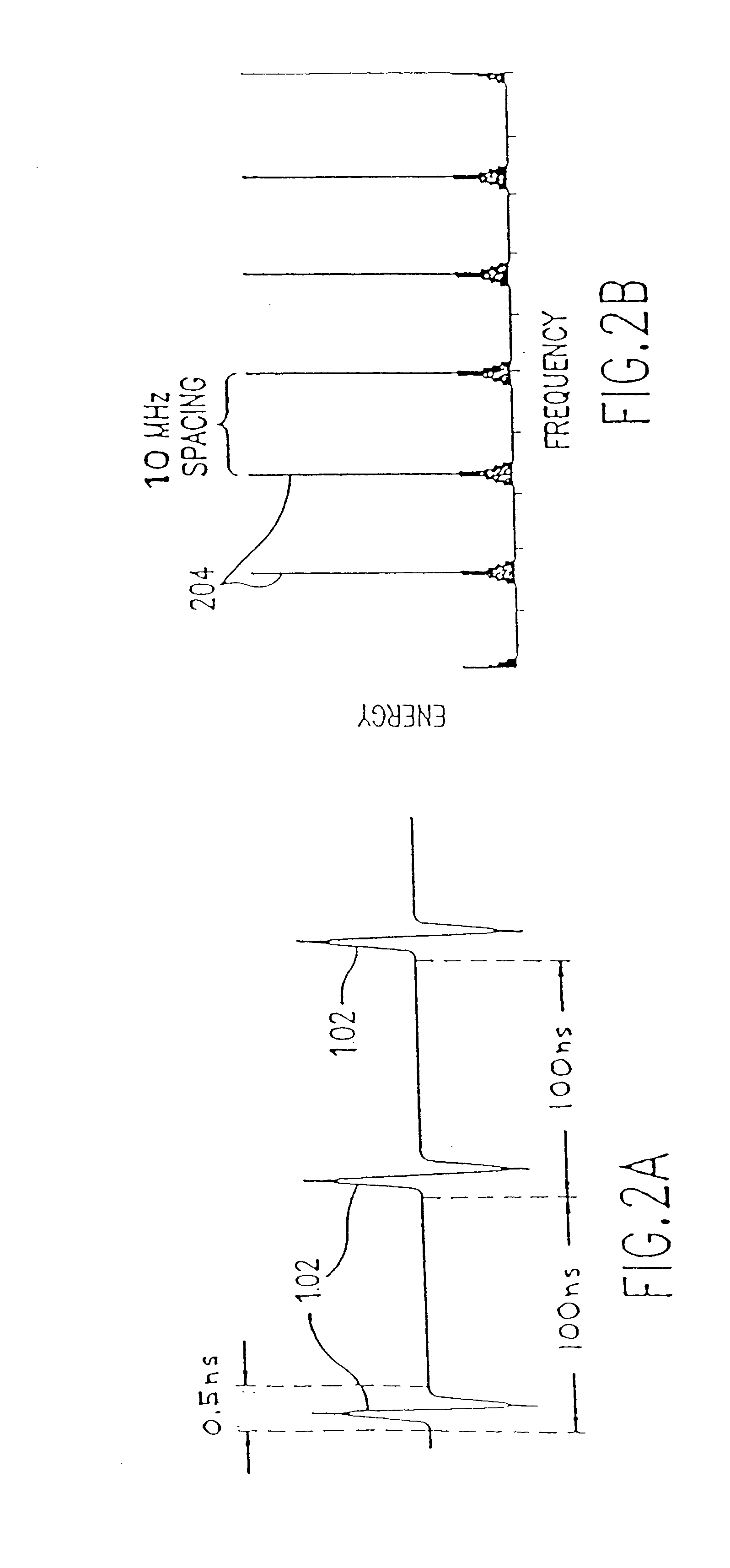
It can also be observed from FIG. 2A that impulse radio systems typically have very low average duty cycles resulting in average power significantly lower than peak power.
Since a data bit may comprise hundreds of pulses, this represents a substantial attenuation of the unwanted channel.
Clearly, if there were a large number of impulse radio users within a confined area, there might be mutual interference.
This is critical as any other signals within the band occupied by an impulse
signal potentially interfere with the impulse radio.
Since there are currently no unallocated bands available for impulse systems, they must share spectrum with other conventional radio systems without being adversely affected.
Without coding, the cross correlation would sample the interfering
signal 402 with such regularity that the interfering signals could cause significant interference to the impulse radio
receiver.
However, when the transmitted impulse signal is encoded with the code
dither (and the impulse radio receiver template signal 406 is synchronized with that identical code
dither) the correlation samples the interfering signals non-uniformly.
This results in possible summation or possible cancellation, depending on the specific propagation to a given location.
In mobile systems, this results in wild
signal strength fluctuations as a function of distance traveled, where the changing mix of multipath signals results in
signal strength fluctuations for every few feet of travel.
This characteristic has been the subject of much research and can be partially improved by such techniques as antenna and frequency diversity, but these techniques result in additional complexity and cost.
Narrow band systems, on the other hand, are limited to the modulation envelope and cannot easily distinguish precisely which RF cycle is associated with each data bit because the cycle-to-cycle amplitude differences are so small they are masked by link or
system noise.
Such `random-like` codes are attractive for certain applications since they tend to spread spectral energy over multiple frequencies while having `good enough` correlation properties, whereas designed codes may have superior correlation properties but have
spectral properties that may not be as suitable for a given application.

