Apparatus and method for measuring optical signal-to-noise ratio

a technology of optical signal and noise ratio, applied in the field of optical communication, can solve the problems of inability to eliminate the noise of the same wavelength of the signal, the inability to measure the noise directly, and the inability to measure the optical signal-to-noise ratio

Inactive Publication Date: 2003-12-30
KOREA ADVANCED INST OF SCI & TECH
View PDF7 Cites 21 Cited by
  • Summary
  • Abstract
  • Description
  • Claims
  • Application Information

AI Technical Summary

Problems solved by technology

The optical amplifier produces not only the amplified optical signals but also the noise of wide wavelength band.
Even though optical filters are used to remove the noise included in the output beam of the optical amplifier, the noise of same wavelengths of the signals can not be eliminated.
However, the noise can not be measured directly since the noise are detected with the optical signals as shown in FIG. 1.
However, in some cases, it is impossible to measure the optical signal-to-noise ratio with the above method in FIG. 2. FIG. 3 explains these cases, and shows another power spectrum of the output beam when optical filters are used to remove the noise in WDM optical communications.
In cases of FIG. 3, the method in FIG. 2 can not be used since the noise is not easily distinguishable from the optical signals.
On the other hand, the noise from an optical amplifier is 100% unpolarized since the noise consists of the randomly occurred lights of all polarization states.
And the method has two major problems; (1) long operation time to measure the optical signal-to-noise ratio, and (2) a complicated active control circuit to handle the polarization controller (401).

Method used


Image

  • Apparatus and method for measuring optical signal-to-noise ratio
  • Apparatus and method for measuring optical signal-to-noise ratio
  • Apparatus and method for measuring optical signal-to-noise ratio

Examples


Embodiment Construction

The present invention will be better understood with regard to the following description, appended claims, and accompanying figures.

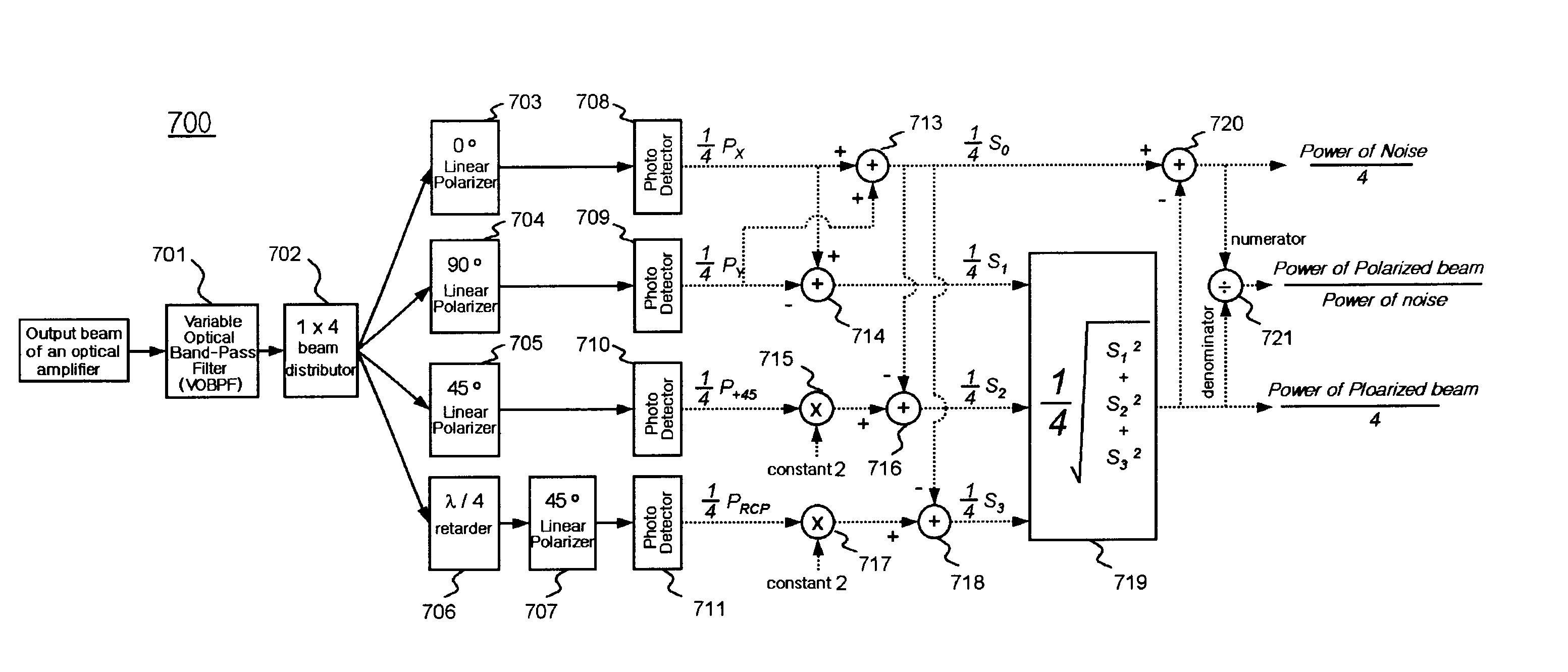
FIG. 7 is a block diagram of the apparatus (700) for measuring optical signal-to-noise ratio according to the present invention. The apparatus of the invention composes a VOBPF (701), an 1.times.4 beam distributor(702), 4 linear polarizers (703, 704, 705, 707), .lambda. / 4 retarder (706), 4 photo detectors (708, 709, 710, 711), 5 adders (713, 714, 716, 718, 720), 2 multipliers (715, 717), a signal processor (719), and a divider (721).

The VOBPF (701) passes the amplified output beam whose wavelength is same as the selected passing wavelength of the VOBPF. The 1.times.4 beam distributor (702) distributes the passing beam of the VOBPF into four streams, and the distributed beams are guided into the 0.degree., 90.degree., 45.degree. LP (703, 704, 705), and the .lambda. / 4 retarder (706). The 0.degree. LP (703) passes only the 0.degree. linear polarization bea...


PUM


Abstract

An apparatus and method for measuring optical signal-to-noise ratio in optical communications includes (1) a variable optical band-pass filter (VOBPF) that passes the amplified output beam when the beam wavelength is the same as the passing wavelength of the VOBPF; (2) a 1x4 beam distributor for distributing the passing beam of the VOBPF into four streams; (3) a measuring device for measuring Stokes parameters S0, S1, S2, S3 from the four distributed beams; (4) a calculating device for calculating the optical signal power by finding the power of the polarized component of the amplified output beam from the Stokes parameters S1, S2, and S3; (5) a calculating device for calculating the noise power by finding the power of the noise included in the amplified output beam from Stokes parameter S0 and the optical signal power; and (6) a dividing device for calculating the ratioat the passing wavelength.

Description

1. Field of the InventionThe present invention relates generally to optical communications, and more particularly relates to an apparatus and a method for measuring optical signal-to-noise ratio in optical communications. An optical amplifier is a device to amplify optical signals without photo-electric / electric-photo conversion, and does not depend on the transmission speed or the transmission format of optical signals. A conventional optical transmitter amplifies the signals after photo-electric conversion, and reproduces optical signals with electric-photo conversion. The optical amplifier is substituted for the conventional optical transmitter. In particular, the optical amplifier can simultaneously amplify many optical signals of different wavelengths in a wide band, and the optical amplifier plays an important role in Wavelength Division Multiplexing (WDM) optical communications. In order to increase the transmitting capacity, several channels of optical signals are multiply d...

Claims


Application Information

Patent Timeline
Patent Type & Authority Patents(United States)
IPC IPC(8): H04B10/08G01J4/00G01J4/04G01J3/51H04B10/00H04B10/07H04B10/29H04B17/00
CPCH04B10/07955H04B10/077G01J4/04H04B10/07H04B10/291
Inventor LEE, CHANG HEESHIN, SANG YUNGCHU, KWANG UK
Owner KOREA ADVANCED INST OF SCI & TECH
Why Eureka
Try Eureka