Carrier detecting circuit for detecting the level of a received signal and communication apparatus

a technology for receiving signals and carrier detection circuits, applied in multiplex communication, transmission monitoring, pulse techniques, etc., can solve problems such as power waste, unsuitable carrier detection, and loss of desired signals

Inactive Publication Date: 2003-12-30
NEC CORP
View PDF15 Cites 45 Cited by
  • Summary
  • Abstract
  • Description
  • Claims
  • Application Information

AI Technical Summary

Benefits of technology

According to the present invention, the threshold value for detecting a carrier is measured in a guard time period between a transmission burst and a reception burst. Thus, since the threshold value is adaptively varied, the communication distance for detecting a carrier can be substantially prolonged. Consequently, the communication area can be widened. In addition, a carrier can be prevented from being incorrectly detected against noise and an interference signal of another system.

Problems solved by technology

However, if a low value is set as the predetermined threshold value, an undesired carrier is detected due to an interference wave of another system, reception noise, and so forth.
Thus, the power will be wasted.
In addition, a desired signal will be lost.
Thus, a large noise margin is accomplished.
However, in the above-described related art references, since the threshold value for detecting a received signal corresponding to the level of the electric field is fixed, a carrier may be incorrectly detected due to an external noise and / or an undesired radio wave.
Thus, the reception area is unnecessarily narrowed.
In other words, when a carrier is detected with a predetermined threshold value, the carrier is incorrectly detected and the reception area becomes narrow.
However, it is difficult to set a threshold value corresponding to the operational environment of the system for use.

Method used


Image

  • Carrier detecting circuit for detecting the level of a received signal and communication apparatus
  • Carrier detecting circuit for detecting the level of a received signal and communication apparatus
  • Carrier detecting circuit for detecting the level of a received signal and communication apparatus

Examples


first embodiment

Operation of First Embodiment

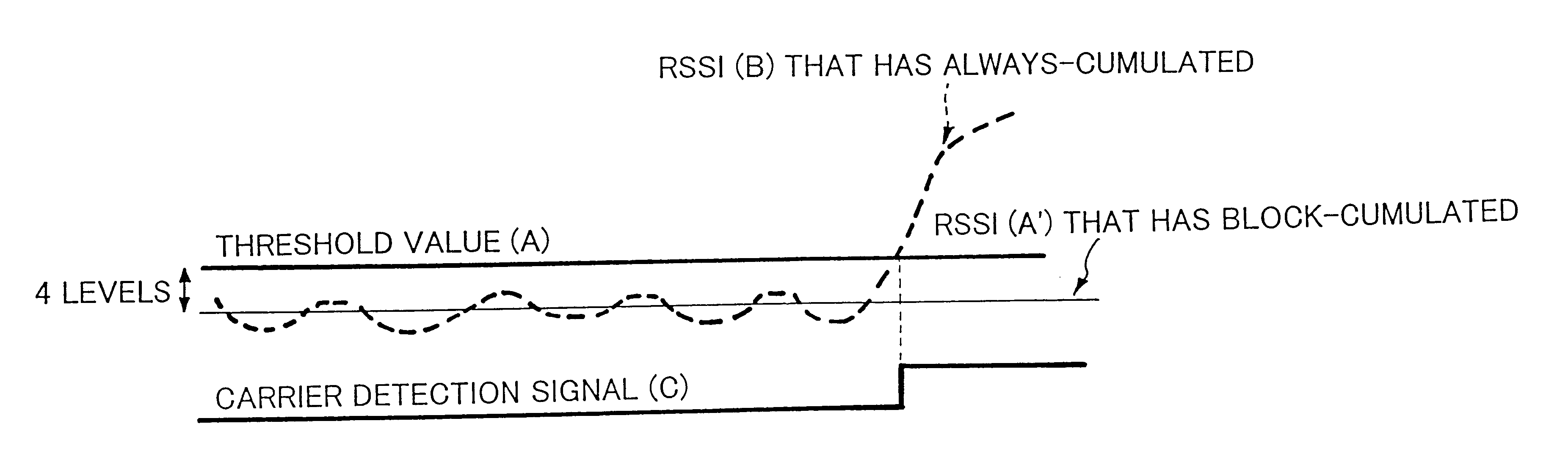
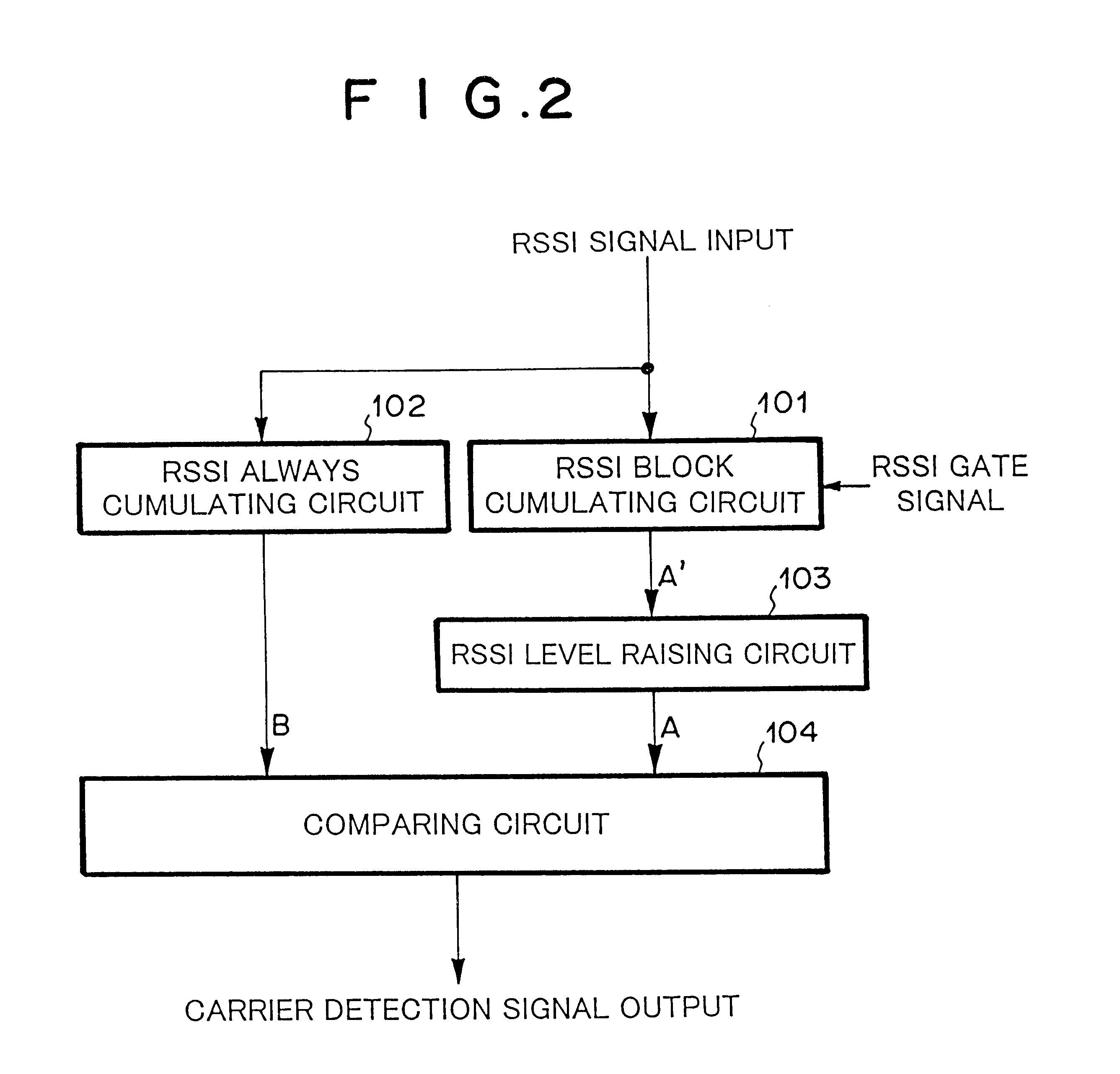
Next, with reference to signal waveforms shown in FIGS. 5 and 6A to 6E, the operation of the first embodiment shown in FIG. 2 will be described. FIG. 5 is a schematic diagram for explaining the operation corresponding to a carrier detection signal (C). RSSI (B) is a waveform of an RSSI signal that has been always-cumulated and smoothed by the RSSI continuous cumulating circuit 102 at the same clock period as the A / D conversion of the RSSI signal. RSSI (A') is a waveform of an output signal that has been block-cumulated and pre-measured by the RSSI block cumulating circuit 101.

As shown in FIG. 5, the RSSI level raising circuit 103 raises the level of RSSI (A') that has been block-cumulated by for example four levels. Thus, the level of the resultant signal becomes the level of the threshold value (A). RSSI (B) that has been always-cumulated fluctuates corresponding to the level of the received signal. When the level of RSSI (B) exceeds the threshold value...

second embodiment

Next, with reference to FIGS. 7 and 8, a second embodiment according to the present invention will be described.

Referring to FIG. 7, a mini mum value detecting circuit 105 is disposed between an RSSI block cumulating circuit 101 and an RSSI level raising circuit 102. The minimum value detecting circuit 105 detects the minimum value of the RSSI signal. According to the first embodiment, the RSSI block cumulating circuit 101 cumulates an RSSI signal while an RSSI gate signal generated in a guard time region in which a burst is not received is active and thereby detects the RSSI signal in a low level. However, according to the second embodiment of the present invention, the RSSI signal is successively cumulated for each cumulative block (for example, the cumulating operation is performed 16 times). The minimum value in a predetermined region is detected by the minimum value detecting circuit 104. The RSSI block cumulating circuit 101, the RSSI level raising circuit 103, the RSSI contin...


PUM


Abstract

An RSSI block cumulating circuit block-cumulates an RSSI signal that has been A / D converted and calculates an RSSI signal in a low level. An RSSI level raising circuit raises the level of the RSSI signal and outputs the resultant signal as a threshold value. An RSSI continuous cumulating circuit always cumulates the RSSI signal. A comparing circuit compares the threshold value with the output signal of the RSSI continuous cumulating circuit and determines whether or not a carrier is present.

Description

1. Field of the InventionThe present invention relates to a carrier detecting circuit for detecting the level of a received signal, in particular, to a carrier detecting circuit for use with a radio receiver and a communication apparatus having the carrier detecting circuit.2. Description of the Related ArtIn such a carrier detecting circuit, a logarithmic amplifier output signal of an RF analog circuit is A / D converted into a received signal strength indicator RSSI. The RSSI is compared with a predetermined fixed threshold value. When the RSSI exceeds the threshold value, a carrier detection signal is output as a trigger for determining whether the received signal has been properly detected.However, if a low value is set as the predetermined threshold value, an undesired carrier is detected due to an interference wave of another system, reception noise, and so forth. Thus, the power will be wasted. In addition, a desired signal will be lost. In contrast, if a high value is set as t...

Claims


Application Information

Patent Timeline
Patent Type & Authority Patents(United States)
IPC IPC(8): H03K9/00H04K1/00H04J3/00H04B17/00H04B1/16H04B1/10H04Q7/22H04B17/318H04L
CPCH04B17/309H04B17/345
Inventor SAKUMA, SHIGERU
Owner NEC CORP
Why Eureka
Try Eureka