Accumulator type fuel injection apparatus

a fuel injection apparatus and accumulation technology, applied in the direction of fuel injecting pumps, machines/engines, electric control, etc., can solve the problems of increased costs, increased costs, seizure, etc., and complication of structur

Inactive Publication Date: 2004-01-06
MITSUBISHI FUSO TRUCK AND BUS CORPORATION
View PDF3 Cites 12 Cited by
  • Summary
  • Abstract
  • Description
  • Claims
  • Application Information

AI Technical Summary

Benefits of technology

post injection control means for controlling the on-off valve to inject additional fuel from the fuel injection nozzle, after the injection of the main fuel by the main injection control means, thereby to raise exhaust temperature of the engine,
Accordingly, the post injection is started at the timing at which the fuel pressure in the fuel passage is higher than a predetermined low pressure, and controlled so that the fuel pressure is to be the predetermined low pressure at the timing at which the post injection ordinary ends. Thus, the predetermined low pressure is maintained when the main injection control means injects the low-pressure fuel (initial injection), and the initial pressure of the post injection becomes the minimum pressure for maintaining the predetermined pressure for the initial injection, so that penetration of the injected fuel is minimized as much as possible and the fuel is well prevented from adhering to the cylinder liner wall. Accordingly, while good main combustion is accomplished and oil dilution, seizure, etc., is well prevented, the exhaust temperature can be raised to quickly activate an after-treatment device.
Here, the reason why the post injection ends at the exhaust stroke end timing is that the post injection cannot contribute to exhaust temperature raising because the additional fuel cannot be exhausted toward an exhaust passage regardless of the post injection performed after an exhaust valve is opened. However, in this case, since the initial pressure of the post injection becomes the minimum pressure in case of the post injection performed before the exhaust stroke end timing, so that the penetration of the injected fuel is minimized as much as possible and the fuel is well prevented from adhering to the cylinder liner wall. In addition, since the fuel pressure of the fuel passage continues to be gradually reduced in an suction stroke after the exhaust stroke, the predetermined low pressure can be maintained at the initial injection timing.
Accordingly, at least the predetermined low pressure can be maintained at the time of the initial injection by the main injection control means. In addition, the post injection can be performed at the timing at which the fuel pressure in the fuel passage is lowered to the predetermined low pressure, so that so that penetration of the injected fuel is minimized as much as possible and the fuel is well prevented from adhering to the cylinder liner wall. Accordingly, while good main combustion is accomplished and oil dilution, seizure, etc., is well prevented, the exhaust temperature can be raised to quickly activate an after-treatment device.

Problems solved by technology

However, providing such a separate heat source leads not only to complication of structure, but also to an increase in costs and is not preferred.
Thus it is feared that the fuel might adhere to the cylinder liner wall, causing oil dilution, seizure, etc., to occur.
However, since the post injection temporally lowers the fuel pressure in a fuel passage communicating with a fuel nozzle or in the accumulator having the low-pressure fuel.
Therefore, it is feared that it might be made impossible to maintain a sufficient fuel pressure, regardless that fuel is injected at a predetermined low pressure in the initial injection.
The insufficient fuel pressure in the initial injection cannot accomplish a target combustion in the main combustion.
Thus, in the event that the post injection raises the exhaust temperature to quickly activate an oxidation catalyst, a continuous regeneration DPF, or an NOx catalyst, a problem arises as to how the fuel pressure at the post injection time is minimized as much as possible for preventing oil dilution, seizure, etc., while a sufficient fuel pressure is provided at the initial injection time to realize favorable main combustion.
Here, the reason why the post injection ends at the exhaust stroke end timing is that the post injection cannot contribute to exhaust temperature raising because the additional fuel cannot be exhausted toward an exhaust passage regardless of the post injection performed after an exhaust valve is opened.

Method used


Image

  • Accumulator type fuel injection apparatus
  • Accumulator type fuel injection apparatus
  • Accumulator type fuel injection apparatus

Examples


first embodiment

To begin with, a first embodiment will be discussed.

FIG. 4 is a flowchart to show a control routine of post injection control according to the first embodiment. The control routine will be discussed with reference to the flowchart.

At step S10, whether or not raising the exhaust temperature is required is determined based on whether or not the PM deposition amount exceeds a predetermined value.

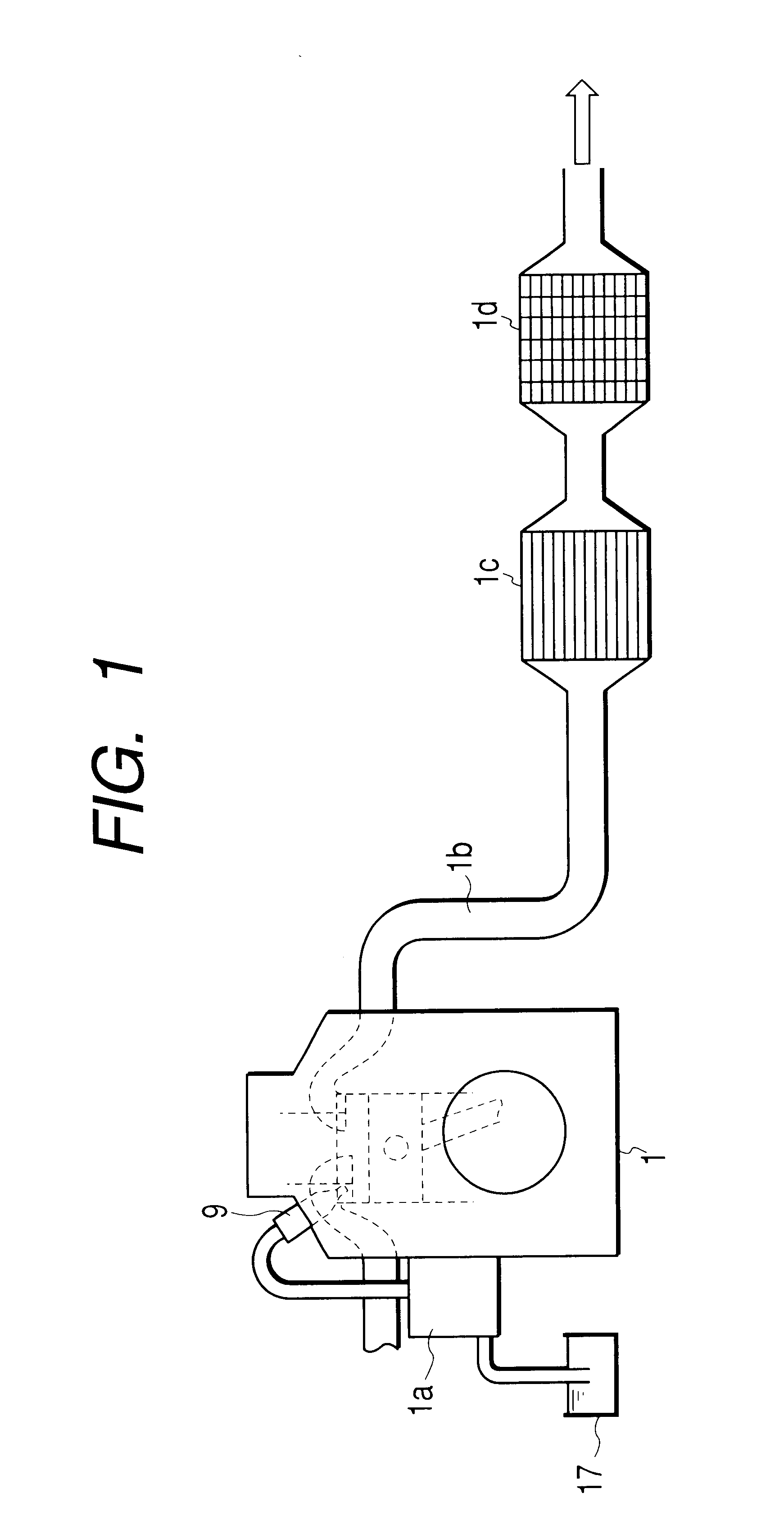
The reason why whether or not raising the exhaust temperature is required is determined based on whether or not the PM deposition amount becomes greater than the predetermined value is that when the exhaust system temperature is low and the continuous regeneration DPF including the DPF 1d and the oxidation catalyst 1c cannot serve the continuous regeneration function, the PM deposition amount increases and as the PM deposition amount is monitored, the exhaust system temperature being low can be easily detected. In case of the exhaust temperature rising, PM is burnt and rapidly generates heat as...

second embodiment

Next, a second embodiment will be discussed.

FIG. 9 is a flowchart to show a control routine of post injection control according to the second embodiment. The control routine will be discussed with reference to the flowchart.

At step S30, whether or not raising the exhaust temperature is required is determined based on whether or not the PM deposition amount exceeds a predetermined value as at step S10 in FIG. 4.

At step S32, steps S12 to S28 in FIG. 4 in the first embodiment are executed and the injector 9 is driven at a similar injection timing for performing post injection.

At step S34, a timer is reset (t=0) at the same time as the post injection is started, and at step S36, whether or not the count time t of the timer reaches the injection time period tpost is determined. If the determination result is false (NO), a wait is made for the count time t to reach the injection time period tpost. On the other hand, if the determination result is true (YES) and the count time t is determi...


PUM


Abstract

A common-rail injection system includes a first accumulator of high pressure and a second accumulator of low pressure. The common-rail injection system includes a post injection control device for injecting additional low-pressure fuel from the second accumulator through a fuel injection nozzle after main fuel is injected. The post injection control device injects the additional fuel the injection terminates at a first timing when the fuel pressure in either fuel passage or second accumulator lowers to a predetermined value lower than that of the high-pressure fuel or at a second timing when an exhaust stroke of the engine is completed, whichever earlier.

Description

1. Field of the InventionThis invention relates to an accumulator type fuel injection apparatus and more particularly to a fuel injection control technique for activating an exhaust emission purifier in a diesel engine.2. Description of the Related ArtExhaust gases emitted from a diesel engine mounted in a bus, truck, etc., contain much particulate matter (PM) as well as HC, CO, NOx, etc. A diesel particulate filter (DPF) has been put into practical use as an after-treatment device of a diesel engine. The DPF captures PM, and burns and removes the captured PM with an external heat source and an oxidation catalyst for treating HC and CO. Recently, a continuous regeneration DPF has been designed wherein a catalyst that generates NO.sub.2 for supplying an oxidant to oxidize and remove PM is placed upstream of the DPF in place of the external heat source of the DPF, so as to continuously remove the PM on the DPF by the generated NO.sub.2. Further, insertion of an NO.sub.x catalyst has a...

Claims


Application Information

Patent Timeline
Patent Type & Authority Patents(United States)
IPC IPC(8): F02M63/00F02M63/02F02D41/40F02M45/00F02M47/02F02D41/02F02B3/00F02B3/06F01N3/02F01N3/023F01N3/035F02M45/02F01N3/24F01N13/02F02D41/38F02M45/04F02M47/00F02M55/02
CPCF01N3/0231F01N3/035F02M45/00F02M47/027F02M63/0225F01N13/009F01N2250/02F02B3/06F02D41/029F02D41/402F02D2041/3881F02D2200/0602F02D2250/11F02D2250/31F02M45/04F02M47/00
Inventor NAKAYAMA, SHINJIKOHKETSU, SUSUMUTANABE, KEIKI
Owner MITSUBISHI FUSO TRUCK AND BUS CORPORATION
Why Eureka
Try Eureka