Pneumatic transfer terminal and method of operation

a technology of pneumatic transfer and terminal, which is applied in the directions of atm details, instruments, transportation and packaging, etc., can solve the problems of customer lessening security, unable to surrender card, and unable to meet customer requirements,

a technology of pneumatic transfer and terminal, which is applied in the directions of atm details, instruments, transportation and packaging, etc., can solve the problems of customer lessening security, unable to surrender card, and unable to meet customer requirements,

US6672808B1Inactive Publication Date: 2004-01-06DIEBOLD NIXDORF

Image

  • Pneumatic transfer terminal and method of operation
  • Pneumatic transfer terminal and method of operation
  • Pneumatic transfer terminal and method of operation

Examples


Embodiment Construction

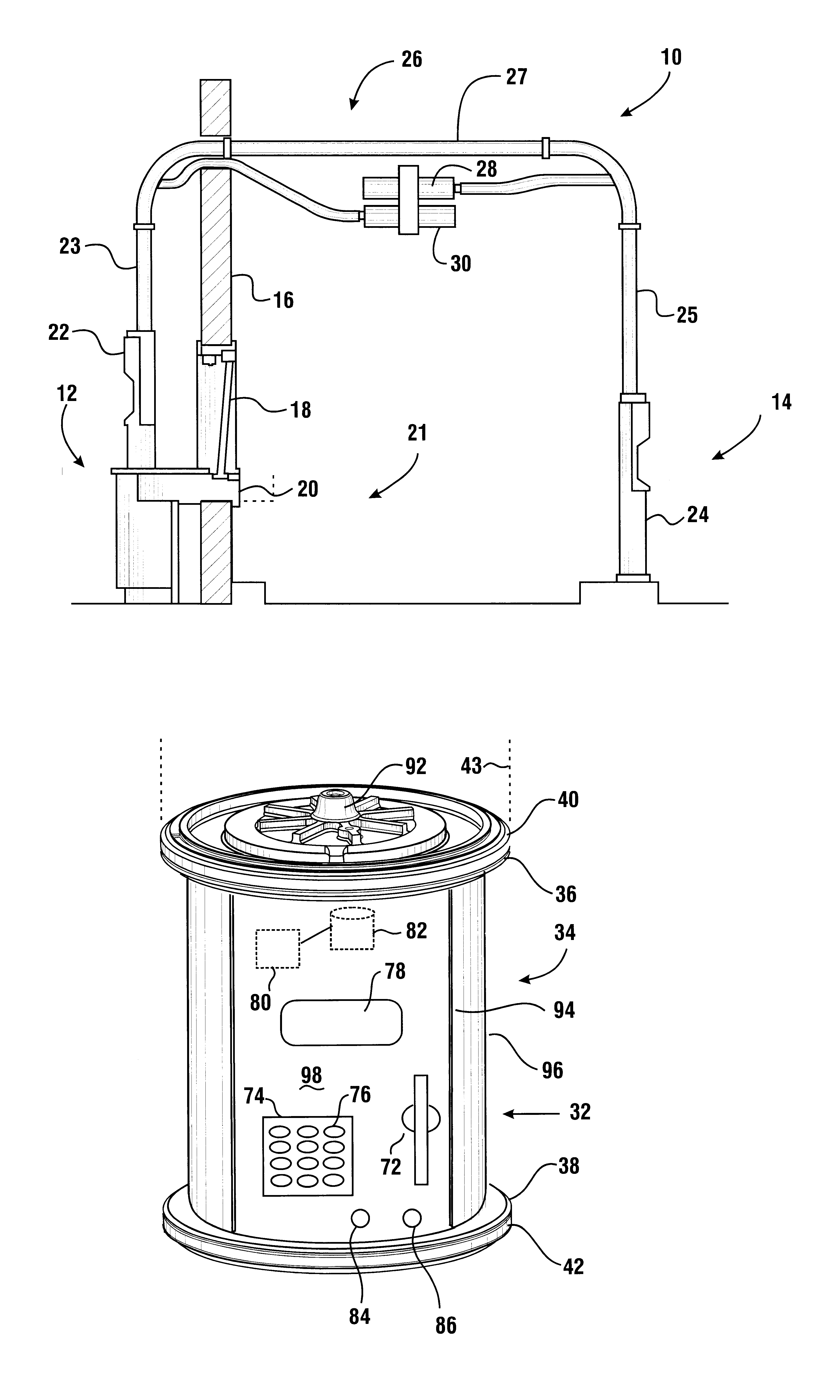
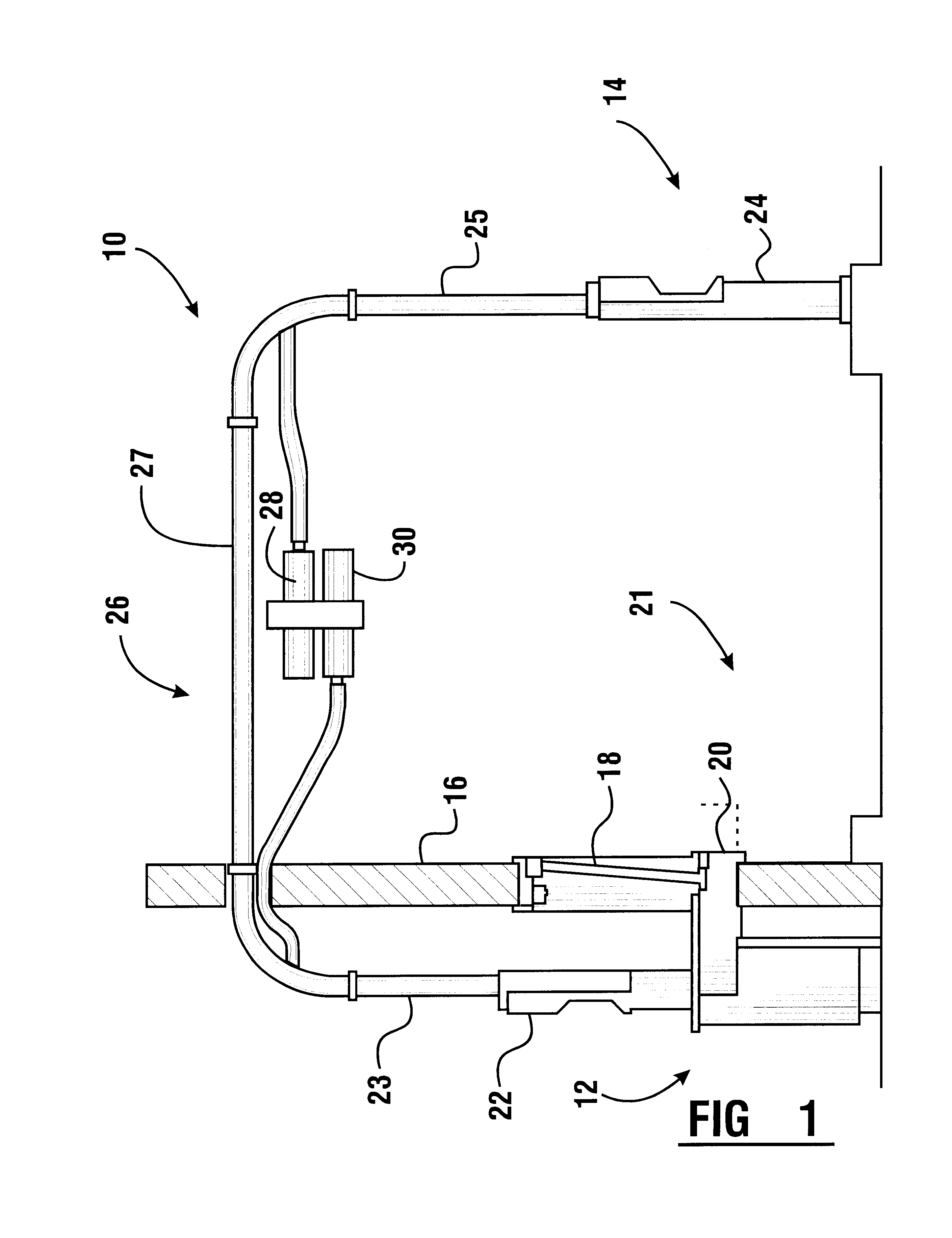
Referring now to the drawings and particularly to FIG. 1, there is shown therein an exemplary embodiment of the transaction system incorporating an exemplary form of the present invention, generally indicated 10. The transaction system 10 includes a service provider station, generally indicated 12, and a customer station, generally indicated 14. In an exemplary embodiment, the service provider station is positioned within a facility in which goods or services are sold. In one exemplary embodiment, the service provider station is positioned adjacent to a pharmacy operation which enables pharmacy items, such as medications, to be delivered to customers adjacent to the customer station 14. In the exemplary embodiment, customer station 14 is positioned adjacent to a drive-through lane in which customers may carry out transactions while positioned in a vehicle.

In the exemplary embodiment, the service provider station is also positioned adjacent to a drive-through window 18. A movable dra...


PUM


Abstract

A system (10) for carrying out transactions between a customer at a customer station (14) and a service provider at a service provider station (12), includes transferring a body (96, 140, 170) through a pneumatic transfer tube (26). The customer at the customer station provides inputs corresponding to a financial account through input devices on the body such as a card reader (72, 146, 172) and a keypad (74, 148, 172). Data input by the customer is stored in the memory (82, 158) on the body. After transfer to the service provider station, data in the memory is output to a charge device (56) which is operative to assess a charge to the customer's account responsive to data output from the memory.

Description

This invention relates to transaction systems. Specifically, this invention relates to a system in which transactions are carried out between a service provider and remotely located customers through a pneumatic transfer apparatus, and in which system the customers may charge amounts associated with their transactions to their accounts without having to give to the service provider their credit card, debit card or other item corresponding to their account.Pneumatic transfer systems which may be used to carry out transactions are known in prior art. Such systems may be used to conduct transactions between a service provider and remotely located customers. Such systems have been used in drive-through banking applications as well as in other transaction environments. Such systems are shown in U.S. Pat. Nos. 5,299,891 and 6,146,057, which are owned by the assignee of the present invention and the disclosures of which are incorporated herein by reference.In many types of transaction syst...

Claims


Application Information

Patent Timeline
06 Jan 2004
Publication
US6672808B1
IPC
B65G51/00; B65G51/06; G07F19/00
CPC
B65G51/04; B65G51/06; G07F19/20; G07F19/205
Inventors
MCINTYRE, DANIEL S.; REESE, RODNEY J.