
Modular terminal block assembly

a module terminal and assembly technology, applied in the direction of coupling device details, coupling device connections, contact members penetrating/cutting insulation/cable strands, etc., can solve the problems of limiting the number of components or sections that could be joined together, the modular terminal block cannot hold environmental sealing well, and the attempt to produce an optimal system is still unsatisfactory

Inactive Publication Date: 2004-01-06
EMERSON NETWORK POWER ENERGY SYST NORTH AMERICA
View PDF8 Cites 18 Cited by
  • Summary
  • Abstract
  • Description
  • Claims
  • Application Information

AI Technical Summary

Benefits of technology

"The present invention is a modular terminal block assembly that is robust, effective, and economical. It is designed to provide a reliable connection between individual wires or conductors in a multi-pair cable. The assembly includes two modular shells with insulation displacement connectors mounted on the base wall and side walls of the shells. The assembly also includes activators for joining the modular shells, as well as a universal connector for joining the modular shells. The assembly is environmentally sealing and can be made larger than previous modular block assemblies. It also includes improved conductor strain relief and better containment of gel or grease when the conductors are removed and inserted. The invention solves the problems of previous modular block assemblies and provides a more effective and reliable solution for connecting wires in a cable."

Problems solved by technology

Modular terminal block assemblies tended to have insufficient structural integrity thereby limiting the number of components or sections that were able to be joined together.
Furthermore, modular terminal blocks could not hold environmental sealing well and thus was a constant concern since any moisture that works its way to the electrical connection between the conductor and the connector degrades that connection or causes a failure.
Efforts have been made in the past to improve upon the structure of modular terminal block assemblies but these prior attempts have yet to produce an optimal system.

Method used


Image

  • Modular terminal block assembly
  • Modular terminal block assembly
  • Modular terminal block assembly

Examples


Embodiment Construction

While the present invention is open to various modifications and alternative constructions, the preferred embodiment shown in the various figures of the drawing will be described herein in detail. It is understood, however, that there is no intention to limit the invention to the particular embodiment, form or example disclosed. On the contrary, the intention is to cover all modifications, equivalent structures and methods, and alternative constructions falling within the spirit and scope of the invention as expressed in the appended claims, pursuant to Title 35 U.S.C. section 112 (second paragraph).

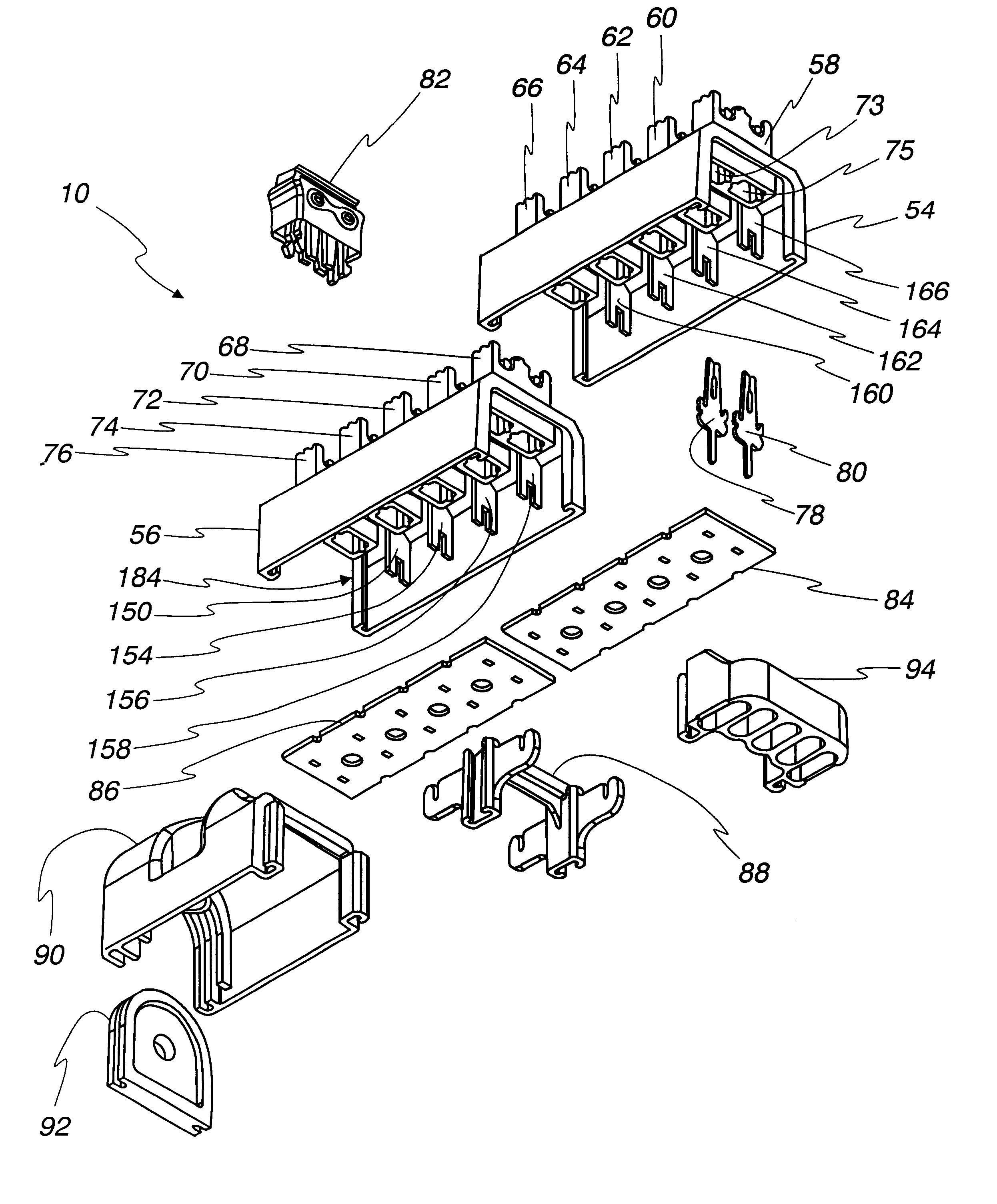
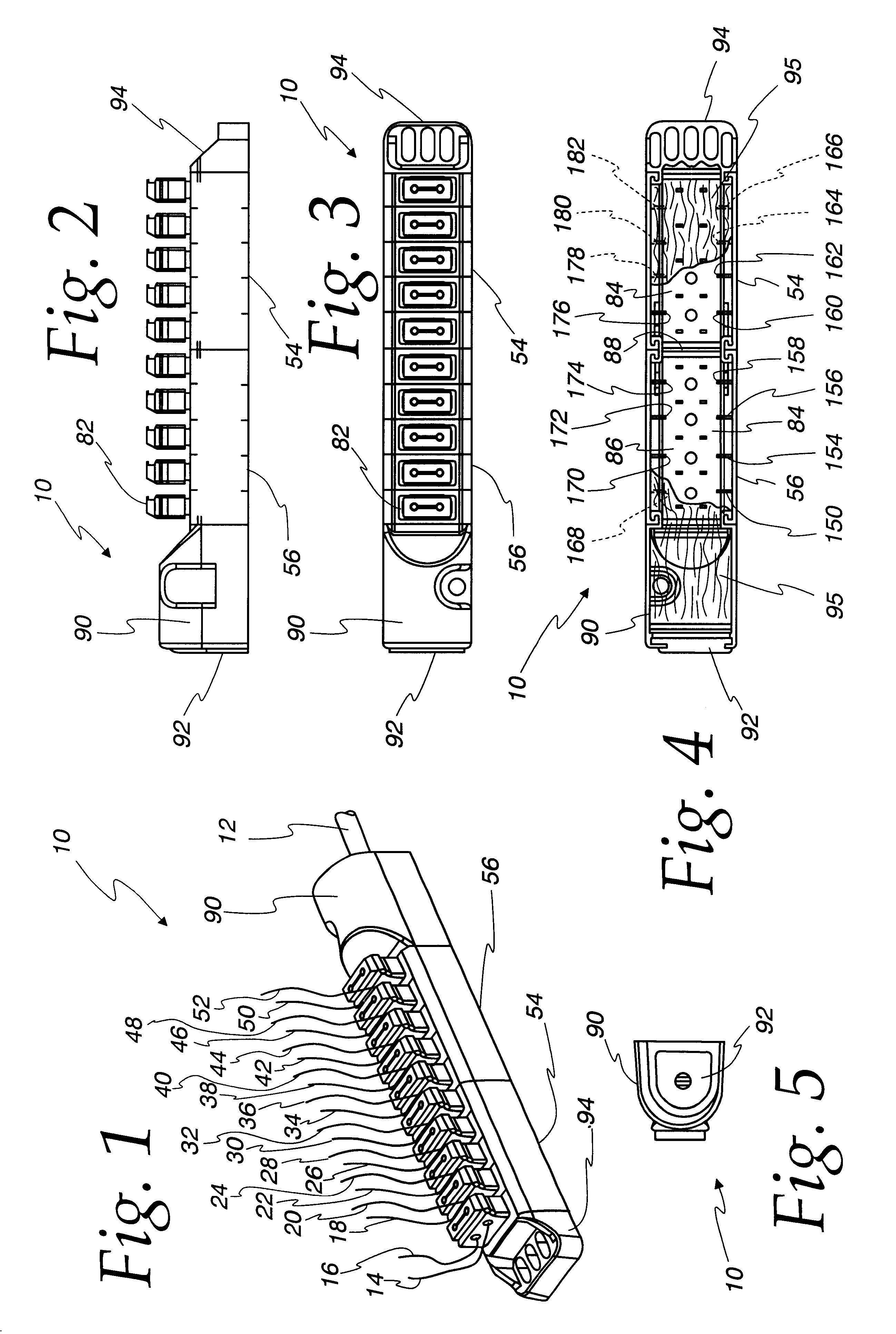
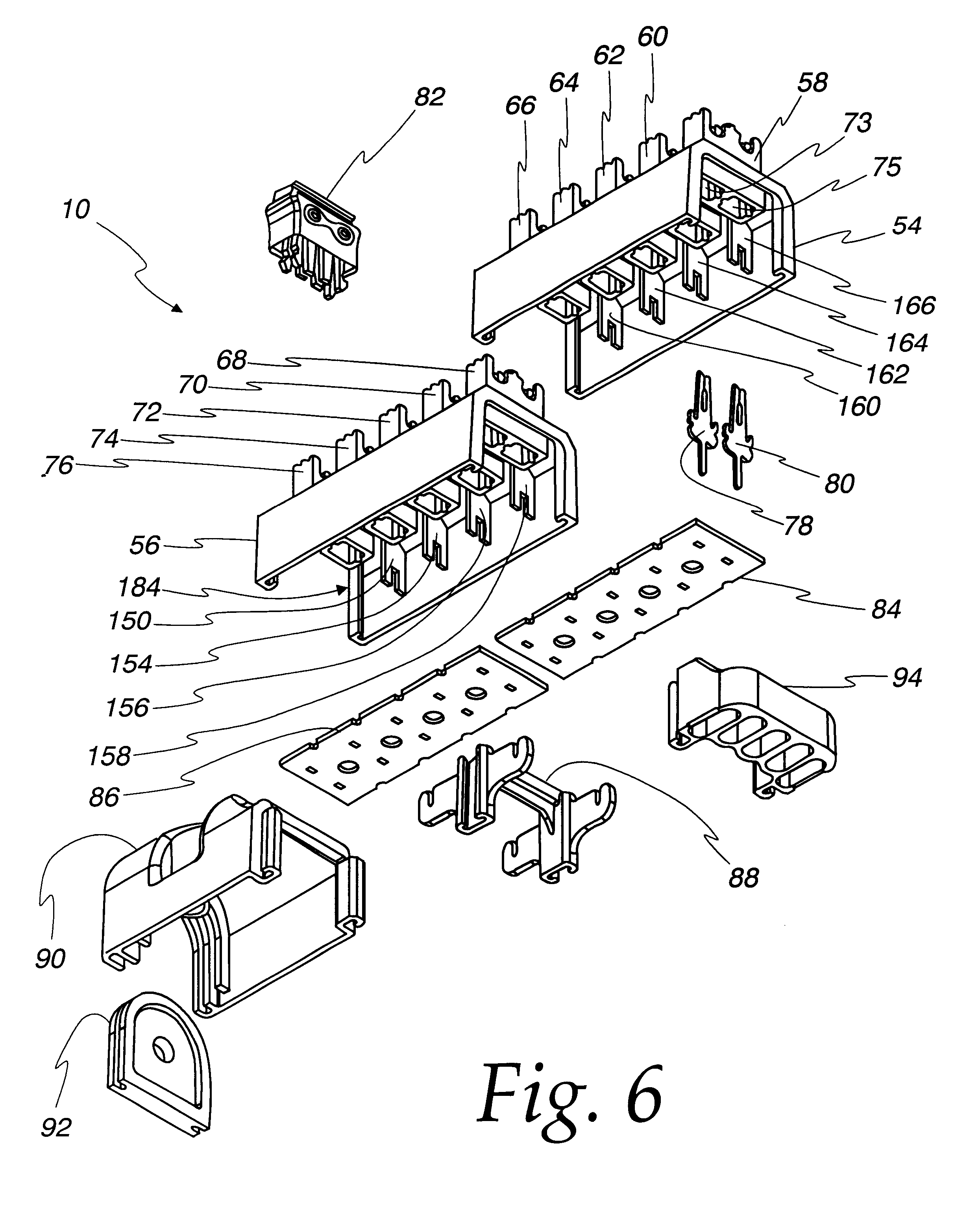
Referring now to FIGS. 1-6, a fully assembled modular terminal block assembly 10 as well as its individual components are illustrated. As explained above, the terminal block assembly may be used to receive a cable 12 from a central office, for example, that contains multiple line pairs that may be used for telephone service. These multiple line pairs are divided in the terminal block ass...


PUM


Abstract

A modular terminal block assembly including modular shells having channel shaped and walled ends, multiple housings for insulation displacements connectors and slotted partitions. A universal connector with extending parallel arms connect abutting modular shells, and barrier strips are located within the modular shells abutting the housings. End shells are also attached to the modular shells. Grease is placed in the housing and in activators mounted to the housings. The shells are filled with potting compound where the arms and partitions integral with the shells act as reinforcing elements in the compound. Thereafter the compound hardens so as to strengthen and stiffen the connected shells. This results in a robust assembly.

Description

Not applicable.STATEMENT RE FEDERALLY SPONSORED RESEARCHNot applicable.1. Field of the InventionThe present invention relates to a modular terminal block assembly and more particularly, to a modular terminal block assembly which is robust, effective and economical.2. Description of the Related ArtTerminal blocks are utilized in the telecommunications industry to provide an efficient connection for individual wires, line or conductors to individual pairs of lines of a multi-pair cable. Such terminal blocks may provide connection, for examples, between a multi pair cable from a central office and line pairs from neighboring subscriber locations.The typical terminal block utilizes insulation displacement connectors sometimes called clips to make the connection. This type of connector pierces the insulation of a wire or conductor as the conductor is inserted into the terminal block by a tool called an activator. The other end of the clip is fixed to an electrical conductor from the cabl...

Claims


Application Information

Patent Timeline
Patent Type & Authority Patents(United States)
IPC IPC(8): H01R13/52H01R13/516H01R13/514H01R4/24H01R4/2416
CPCH01R13/516H01R13/5216H01R4/2433H01R13/514
Inventor SEDLECKY, DANIEL P.BAUM, THOMASAOUF, MOHAMMED G.
Owner EMERSON NETWORK POWER ENERGY SYST NORTH AMERICA
Learn More