Medium carbon steel sheet and strip having enhanced uniform elongation and method for production thereof

a technology of uniform elongation and carbon steel, which is applied in the direction of heat treatment equipment, manufacturing tools, furnaces, etc., can solve the problems of not revealing the steel having high uniform elongation, requiring a substantial amount of capital funds, and high cost of continuous annealing lines having controlled cooling capability, etc., to achieve the effect of reducing yield strength and reducing yield strength

Inactive Publication Date: 2004-01-06
NITED STATES STEEL CORP
View PDF14 Cites 32 Cited by
  • Summary
  • Abstract
  • Description
  • Claims
  • Application Information

AI Technical Summary

Benefits of technology

FIG. 2 is a graph similar to FIG. 1 for a laboratory melted, hot rolled and annealed steel nominally containing 0.5% C, 0.5% Mn, 0.04% Si showing the effect on uniform elongation and lower yield strength at three different hot roll finishing temperatures.
FIG. 3 is a graph of nominal 0.5% C laboratory heats that were hot rolled to strip, cold rolled and annealed showing the interaction of various levels of manganese and silicon in the steel of this carbon level so as to produce various higher levels of lower yield strength without substantial loss of uniform elongation according to the second embodiment of this invention.

Problems solved by technology

Continuous annealing lines having controlled cooling capability are very expensive and require a substantial outlay of capital funds.
This reference does not disclose steel having high uniform elongation, nor controlling the hot roll finishing temperature to obtain high uniform elongation.
Also this reference does not disclose hot rolling with a lower than normal finishing temperature to obtain enhanced uniform elongation.
The reference does not disclose a sub-critical spheroidizing anneal, nor a steel suitable for deep drawing applications.

Method used


Image

  • Medium carbon steel sheet and strip having enhanced uniform elongation and method for production thereof
  • Medium carbon steel sheet and strip having enhanced uniform elongation and method for production thereof
  • Medium carbon steel sheet and strip having enhanced uniform elongation and method for production thereof

Examples


first embodiment

In a first embodiment for producing the steel in hot rolled and annealed form, a steel slab is made by conventional steelmaking practices and has a composition consisting of in weight percent: 0.30 / 0.70 carbon, 0.75 / 2.0 manganese, up to 1.0 silicon, 0.020 / 0.10 total aluminum, the balance iron and incidental impurities.

The reasons for selecting the above chemical composition are as follows:

Carbon:

In order to provide the steel with a satisfactory level of strength through the presence of spheroidal carbides, the carbon level should be at least 0.30%. When the carbon level is greater than 0.70% the steel becomes difficult to cast by the continuous casting process, ductility decreases below a desirable level, and welding becomes very difficult. Therefore, in the first embodiment of the present invention the carbon content is defined as 0.30 to 0.70%. Preferably the carbon content for the first embodiment is 0.30 to 0.40%.

Manganese:

Manganese is added in steelmaking to control hot-shortne...

example 1

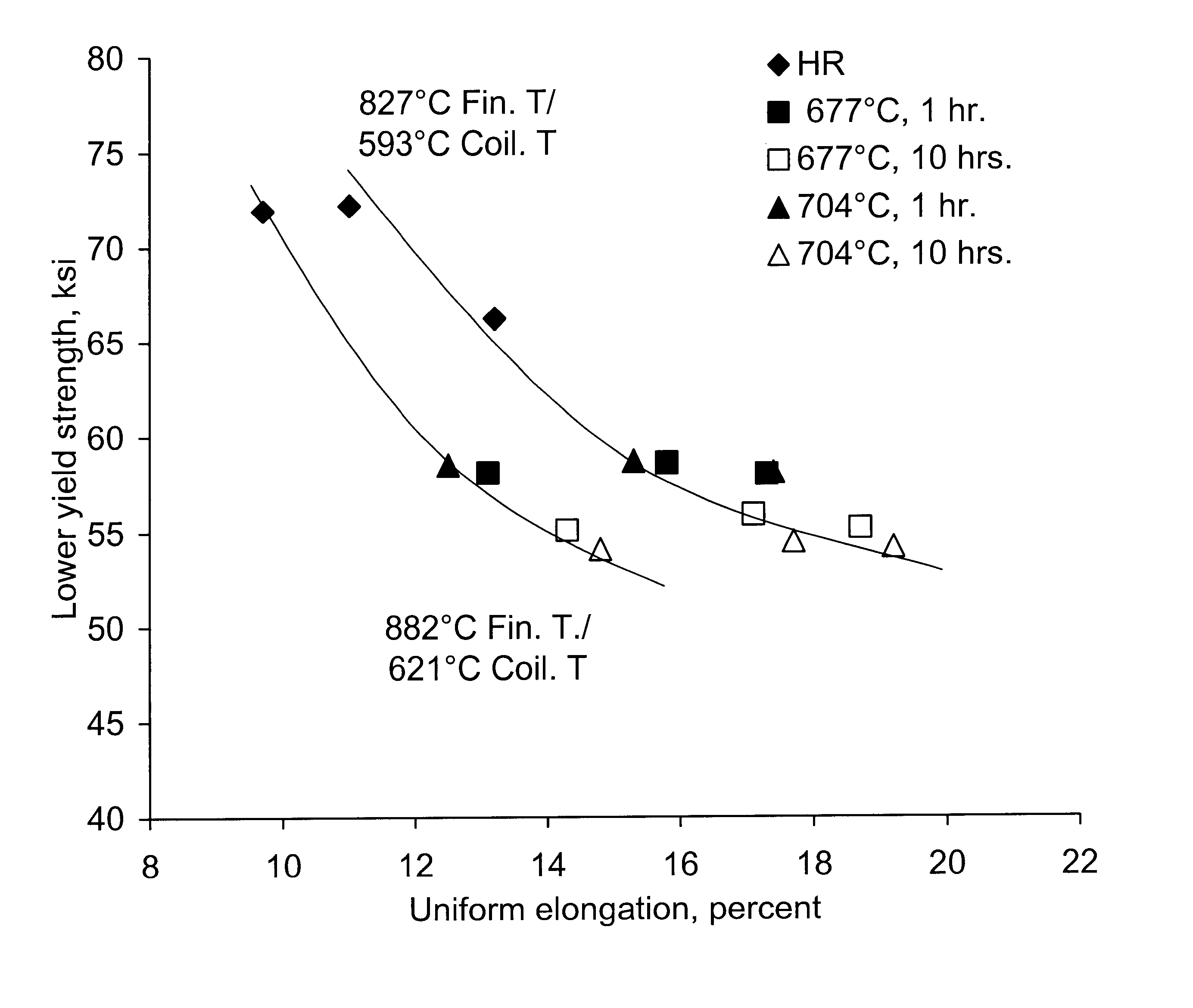
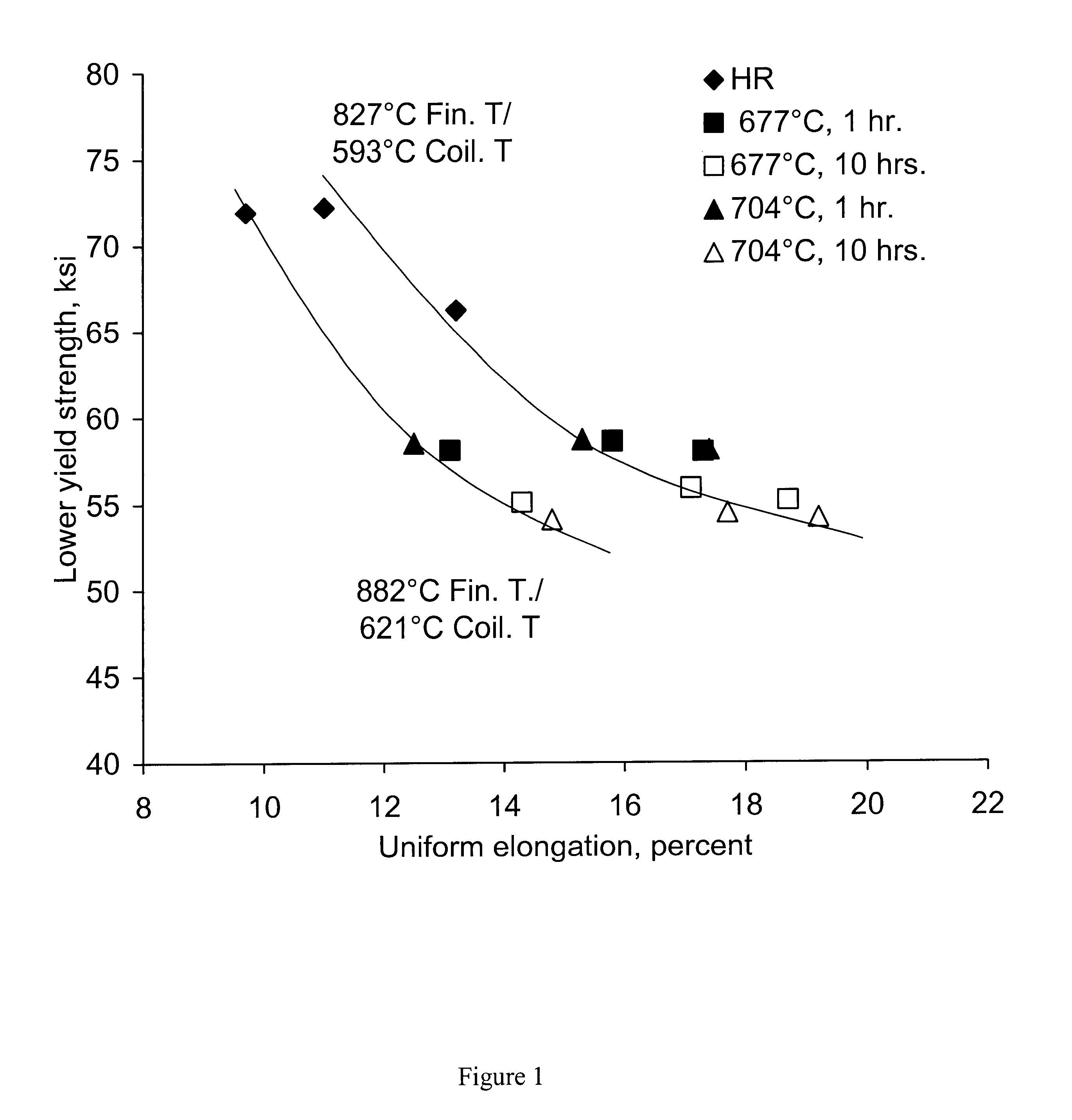
In an example of the first embodiment of this invention a commercial heat of steel was produced by conventional steelmaking and continuous casting. The heat had the following nominal chemical composition in weight percent: 0.35 C, 0.75 Mn, 0.1 Si, and 0.045 Al. Five of the slabs were hot rolled with an aim finishing temperature of 827.degree. C. (1520.degree. F.). The remaining slabs were hot rolled with a normal finishing temperature of 882.degree. C. (1620.degree. F.). The aim coiling temperature for all coils was 593.degree. C. (1100.degree. F.). The coils were pickled and temper rolled. Samples were taken at the temper mill 200 feet from the coil ends and in some cases from the center of the coil. Portions of samples from coils hot rolled at each finishing temperature were annealed in a laboratory furnace for one hour at 677.degree. C. (1250.degree. F.), one hour at 704.degree. C. (1300.degree. F.), and ten hours at each of those temperatures. The results are shown in FIG. 1. FI...

example 2

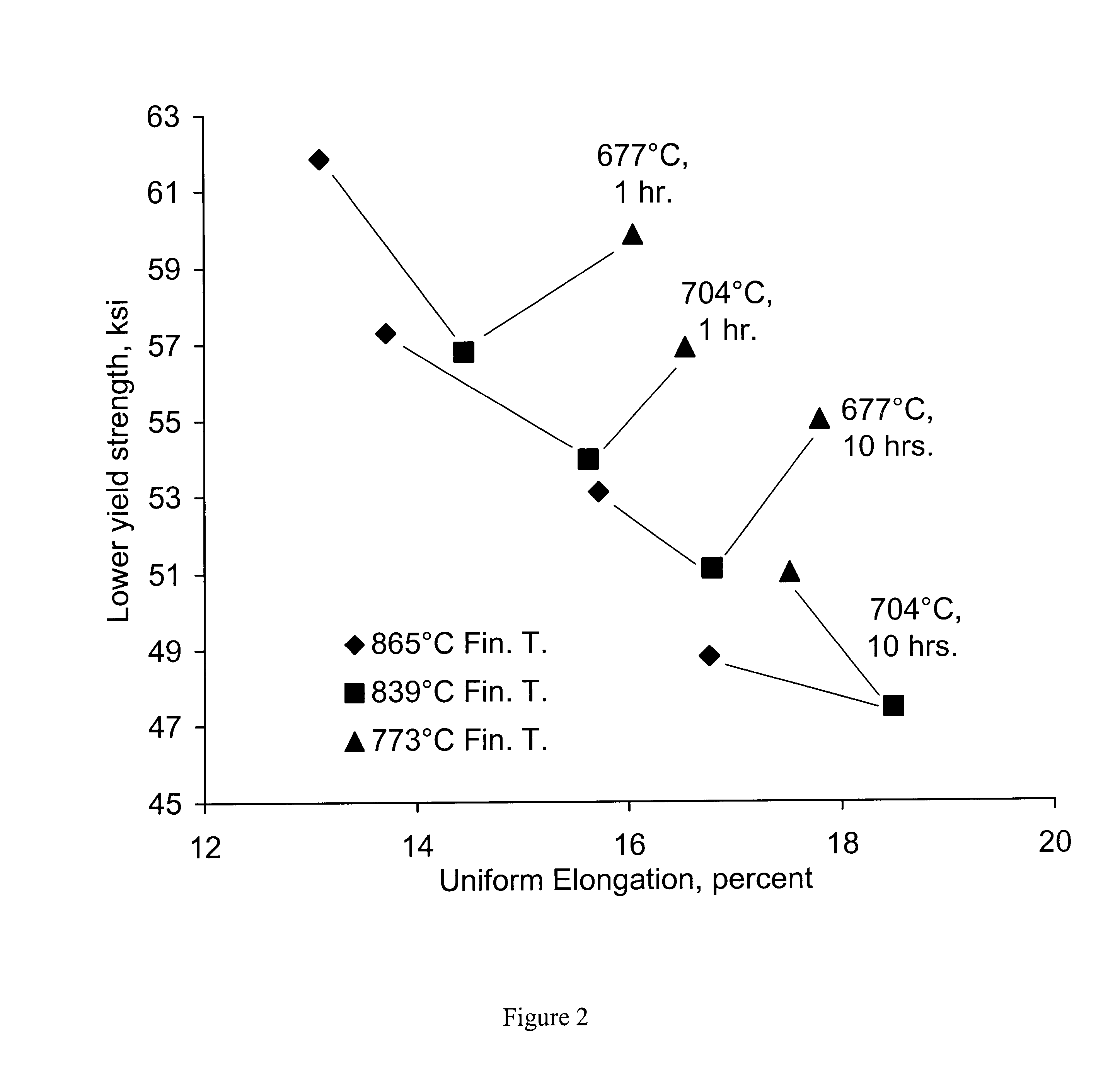
In a second example of the first embodiment of this invention a heat was melted in the laboratory having the following nominal composition: 0.5% C, 0.5% Mn, 0.04% Si. Individual slabs from the heat were hot rolled to strip with one of three hot roll finishing temperatures, 865.degree. C. (1588.degree. F.), 839.degree. C. (1542.degree. F.), and 773.degree. C. (1424.degree. F.). Individual portions of the sample strip from each finishing temperature were annealed for one or ten hours respectively at the same temperatures as in Example 1 above. The results are shown in FIG. 2. FIG. 2 shows that the 839.degree. C. (1542.degree. F.) finishing temperature increased the uniform elongation about 1%. The 773.degree. C. (1424.degree. F.) finishing temperature increased the uniform elongation about 2% (except for the ten hour 704.degree. C. (1300.degree. F.) anneal which appears to be an anomaly) as compared to the results at the 865.degree. C. (1588.degree. F.) finishing temperature.


PUM

PropertyMeasurementUnit
temperatureaaaaaaaaaa
yield strengthaaaaaaaaaa

Abstract

A method is provided for producing medium carbon steel sheet and strip with enhanced uniform elongation for deep drawing applications. In one embodiment, a steel slab containing carbon 0.30 / 0.70%, manganese 0.75 / 2.0%, silicon up to 1.0% max., total aluminum 0.020 / 0.10%, the balance iron and incidental impurities is hot rolled to strip at a finishing temperature within the range of 839° C. (1542° F.) to 773° C. (1424° F.) and spheroidize annealed at a temperature below the A1 temperature. In a second embodiment, a steel slab containing 0.40 minimum / 0.70% maximum carbon, 0.50 / 1.50% manganese, up to 1.0% silicon, 0.020 / 0.10% total aluminum, the balance iron and incidental impurities is hot rolled, cold rolled and spheroidize annealed, with various combinations of manganese and silicon within the above ranges providing lower yield strength at levels of 60 ksi, 70 ksi, and 80 ksi with minimum 14% uniform elongation.

Description

This invention relates to a process for producing medium carbon steel sheet and strip with a spheroidized microstructure having enhanced uniform elongation suitable for deep drawing applications. In one embodiment for producing the steel in hot rolled and annealed form, the steel is hot rolled with a lower than normal finishing temperature and subsequently annealed at a temperature below the A.sub.1 to provide an unexpected increase in uniform elongation. In a second embodiment for producing the steel in cold rolled and annealed form, increased lower yield strength levels are unexpectedly achieved at the higher end of the carbon range without significant decrease in uniform elongation by interaction of Mn and Si at various levels with the higher carbon.There is a need for steel products having high strength and uniform elongation. High uniform elongation is particularly useful where the steel is to be formed into parts for automotive applications. In order to decrease the weight of ...

Claims


Application Information

Patent Timeline
Patent Type & Authority Patents(United States)
IPC IPC(8): C21D1/32C21D8/02C21D1/26
CPCC21D1/32C21D8/0273C21D8/0226C21D8/0236C21D8/0263
Inventor HLADY, CRAIG O.OSMAN, TODD M.
Owner NITED STATES STEEL CORP
Why Eureka
Try Eureka