Retrofit suspension system for a vehicle

Inactive Publication Date: 2004-01-20
PROIA CATALDO
View PDF18 Cites 13 Cited by
  • Summary
  • Abstract
  • Description
  • Claims
  • Application Information

AI Technical Summary

Benefits of technology

One object of the present invention to provide a kit to easily and cost effectively retrofit old vehicles with a suspension system that cause the rear tires to rotate closely along th

Problems solved by technology

Such conventional suspension systems although operable with significant success

Method used


Image

  • Retrofit suspension system for a vehicle
  • Retrofit suspension system for a vehicle
  • Retrofit suspension system for a vehicle

Examples


Embodiment Construction

will be more fully understood with reference to the accompanying drawings in which:

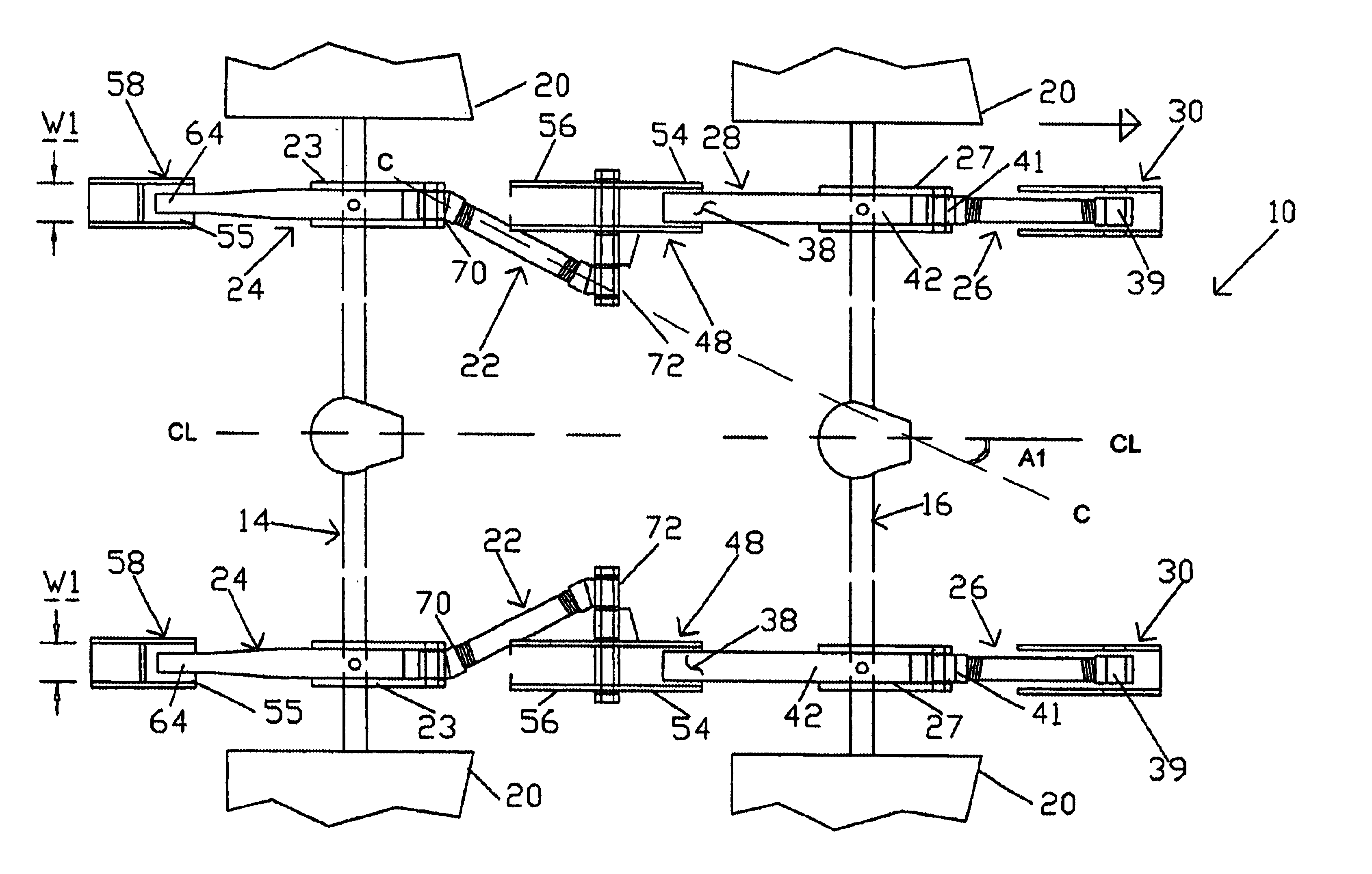
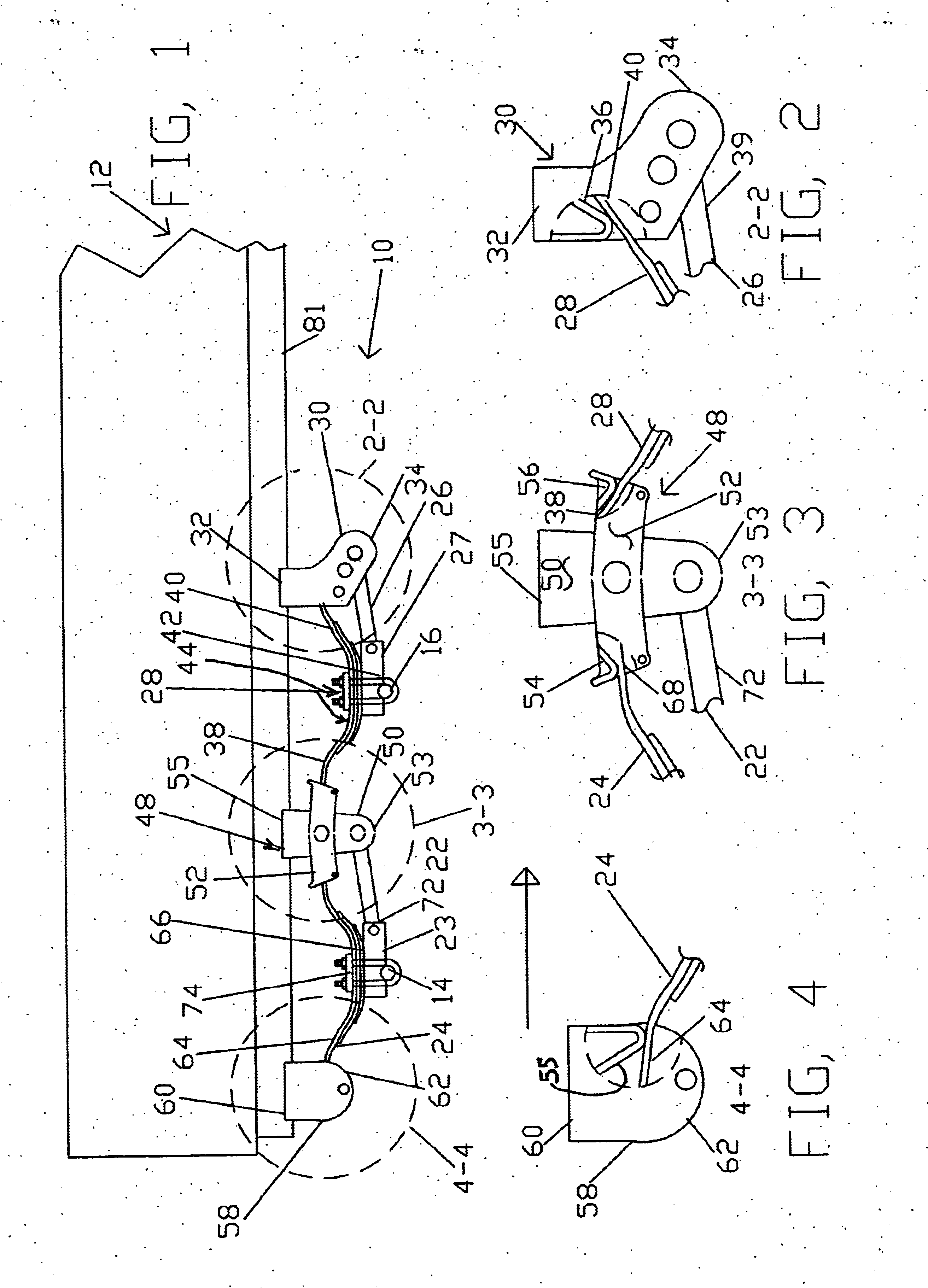
FIG. 1 is a plan view of a two axle vehicle (such as a trailer) retrofitted with the suspension system of the present invention;

FIG. 2 is an exploded view of section 2--2 of FIG. 1;

FIG. 3 is an exploded view of section 3--3 of FIG. 1;

FIG. 4 is an exploded view of section 4--4 of FIG. 1;

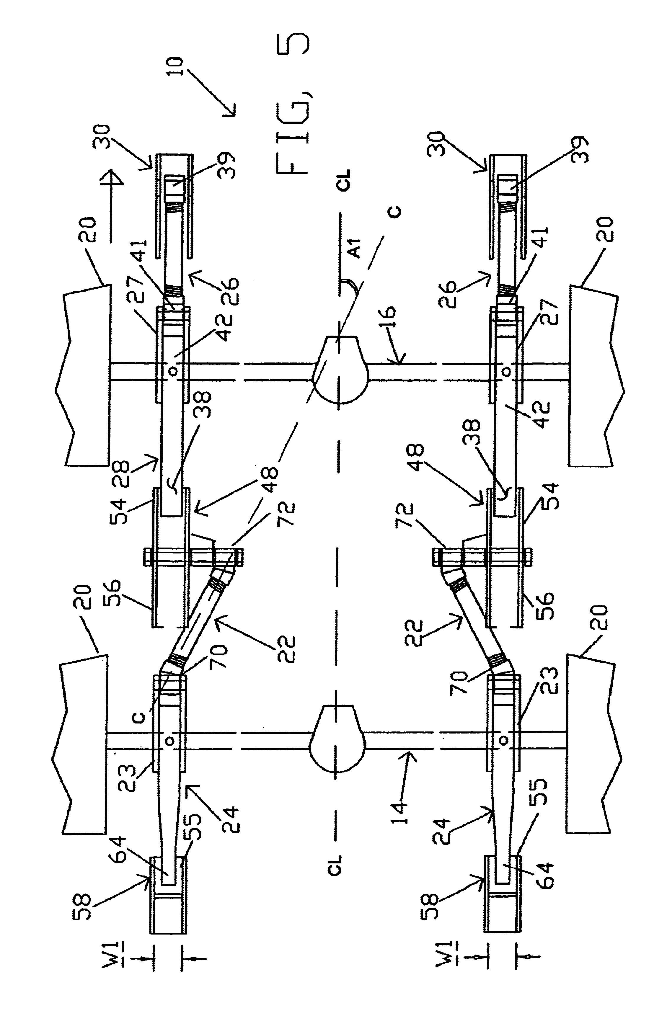
FIG. 5 is plan view of the two axle vehicle retrofitted with the suspension system of the present invention;

FIG. 6 is a plan view of a torque rod and bolt kit of the present invention;

FIG. 7 is an exploded view of the torque rod and bolt kit of the present invention;

FIG. 8 is a side elevation view of the leaf spring of the present invention; and

FIG. 9 is an exploded view of the leaf spring of the present invention.

FIG. 10 is a plan view of a three axle vehicle having retrofitted with the suspension system of the present invention;

FIG. 11 is an exploded view of section 11--11 of FIG. 10;

FIG. 12 is an exploded view of sec...


PUM


Abstract

The present invention is a suspension system for use with a trailer or truck having a frame and front and rear axles. In one embodiment, the suspension system comprises a front hangar having a lower portion, a bearing portion, and an upper portion engaged with the frame. The suspension system further comprises a hangar assembly having a lower portion, an upper portion engaged with the frame and a rocker arm having first and second bearing portions. The suspension system further comprises a rear hangar engaged with the frame and having a bearing portion. The suspension system further comprises a first saddle engaged with the front axle and a second saddle engaged with the rear axle. The suspension system further comprises a leaf spring having a first end portion engaged with the bearing portion of the front hangar and a second end portion engaged with the first bearing portion of the rocker arm. The suspension system further comprises a torque bar having a first end portion engaged with the front hangar and a second end portion engaged with the first saddle of the front axle. The suspension system further comprises a leaf spring assembly comprising an upper leaf spring having a first end portion engaged with the second bearing portion of the rocker arm and a second end portion engaged with the bearing portion of the rear hangar. The first and second end portions of the upper leaf spring have a width that is substantially less than the width of the second bearing portion of the rocker arm and the bearing portion of the rear hangar. The suspension system further comprises a torque bar assembly having a first end portion engaged with the hangar and rocker assembly and a second end portion engaged with the second saddle of the rear axle.

Description

The present invention relates to suspension systems for commercial vehicles.Several suspension systems have been developed which improve the ability a vehicles rear wheels to track the front wheels of the vehicle as it takes a turn around a sharp corner. For example, U.S. Pat. No. 5,220,972 issued to the present inventor on Jun. 22, 1993 (hereinafter the '972 patent) discloses a suspension system for permitting the self-tracking of rear axles by the use of angled torsion rods coupled with means for permitting non-powered lateral deflection of the suspension type employed on the vehicle. With the suspension system of the '972 patent, the rear tires rotate closely along the line of travel of the front tires such that the rear tires track around the corner thereby allowing the driver to safely negotiate a turn without having to use two lanes of traffic. Such conventional suspension systems although operable with significant success may not be cost effective to manufacture and install o...

Claims


Application Information

Patent Timeline
IPC IPC(8): B60G11/10B60G11/02B62D7/14B60P1/04B60P1/28
CPCB60G11/10B60P1/283B62D7/144
Inventor PROIA, CATALDO
Owner PROIA CATALDO
Why Eureka
Try Eureka