Underwater cable protection pipe

a protection pipe and cable technology, applied in the direction of cable installation in underground tubes, sleeves/socket joints, mechanical equipment, etc., can solve the problems of long and fastidious task of the divers installing team, need for two different molds for a more expensive fabrication process, etc., to achieve the effect of reducing weight, reducing labor intensity and reducing labor intensity

Inactive Publication Date: 2004-01-27
IT INT TELECOM
View PDF12 Cites 18 Cited by
  • Summary
  • Abstract
  • Description
  • Claims
  • Application Information

AI Technical Summary

Benefits of technology

Another feature of the present invention is to provide an underwater cable protection pipe which is formed of two identical longitudinal half-pipe sections and which are cast with integrally formed connectors whereby the pipe halves are connected together without the use of bolts or other type fasteners which have to be installed under water.
Another feature of the present invention is to provide an underwater cable protection pipe which is easier, and faster to install and cheaper to produce and wherein the pipe is made of anodized aluminum thereby resulting in a significant reduction in weight as compared to existing ductile iron pipes.

Problems solved by technology

Articulated pipes are used to protect submarine is cables when burial of submarine cables is not feasible due to hard sea bottom or when burial creates environmental concern since it disturbs the seabed sediments.
This means a very long and fastidious task for the divers installing team.
Having two different parts bring other problems, such as, shipment miscount (different number of lowers and uppers at one site) and need for two different molds for a more expensive fabrication process.

Method used


Image

  • Underwater cable protection pipe
  • Underwater cable protection pipe
  • Underwater cable protection pipe

Examples


Embodiment Construction

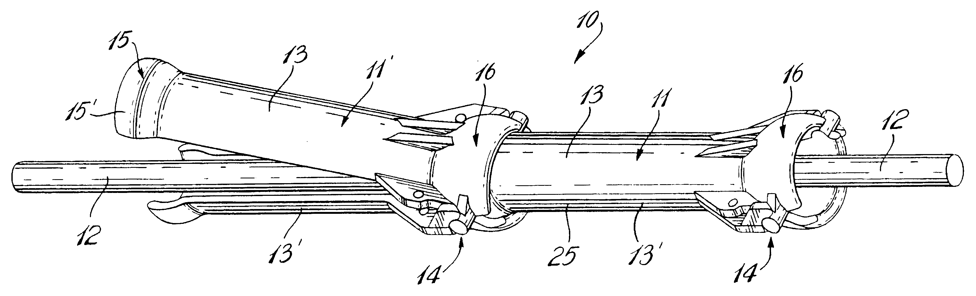
Referring now to the drawings and more particularly to FIG. 1, there is shown generally at 10 two underwater cable protection pipes 11 and 11' which are interconnected end-to-end about an underwater cable 12 to protect the cable. The underwater cable protection pipe 11 is comprised of two identical longitudinal half-pipe sections 13 and 13' which are interconnected together by integrally formed interlocking mating connectors, generally indicated at 14, and which will be described in detail later. As hereinshown when these pipe sections 13 and 13' are interconnected together they form the longitudinal hollow pipe 11.

Each of the half-pipe sections 13 and 13' are cast from anodized aluminum which is much lighter than ductile iron pipes which have heretofore been utilized for underwater protection pipes. The half pipe sections 13, 13' are cast with a stub end 15 and an articulatable clamping ball end 16.

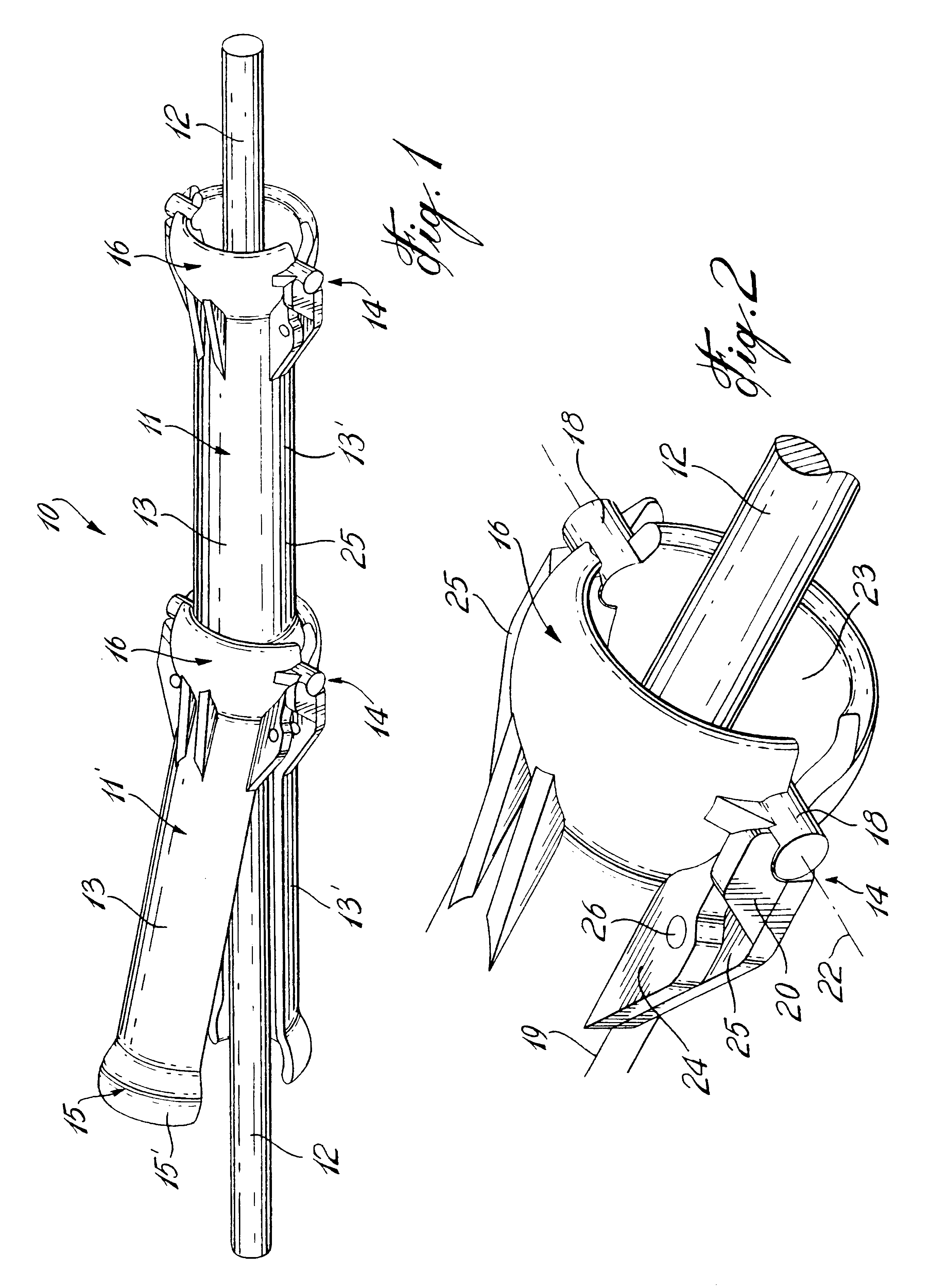
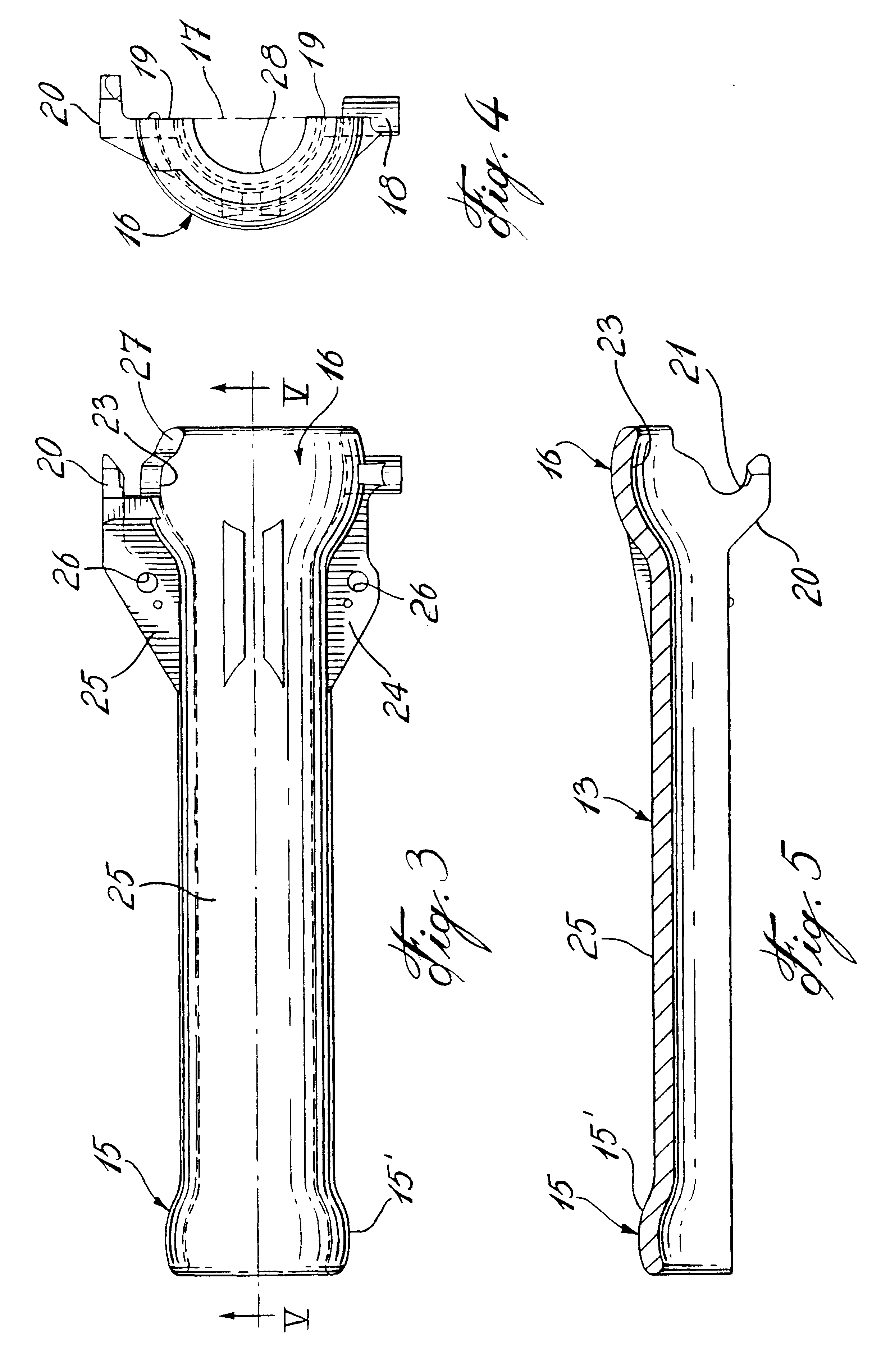
With further reference now to FIGS. 2 to 5, it can be seen that the interlocking con...


PUM


Abstract

An underwater cable protection pipe (11) is comprised of two identical longitudinal half-pipe sections (13, 13') interconnectable with one another by integrally formed mating connectors (14). The half-pipe sections (13, 13'), when interconnected together, form a longitudinal hollow pipe (11) having a stub end (15) and an articulatable clamping ball end (16) shaped to clampingly receive the stub end (15) of a like pipe (11) to interconnect two or more of the pipes (11) end-to-end about a submerged cable (12).

Description

The present invention relates to an underwater cable protection pipe which is formed of two identical longitudinal half-pipe sections interconnected together by integrally formed mating connectors provided at a clamping ball end of the pipe sections and wherein the clamping ball end constitutes an articulated joint when pipes are interconnected together end-to-end.Articulated pipes are used to protect submarine is cables when burial of submarine cables is not feasible due to hard sea bottom or when burial creates environmental concern since it disturbs the seabed sediments. Existing articulated pipes are made of short sections of pipe split in two longitudinal halves. Each section has one small ball type end and one large ball type end. The large ball type end encloses over the small ball end of the previous section holds it captive. This locks the end of the previous section and provides an articulated joint that can adjust itself to the seabed profile.There are two types of existi...

Claims


Application Information

Patent Timeline
Patent Type & Authority Patents(United States)
IPC IPC(8): H02G9/00H02G9/02H02G9/06
CPCH02G9/02H02G9/065H02G3/0475
Inventor POIRIER, NANCY
Owner IT INT TELECOM
Why Eureka
Try Eureka