
Program object for use in generating application programs

Inactive Publication Date: 2004-01-27
NATIONAL INSTRUMENTS
View PDF31 Cites 161 Cited by
  • Summary
  • Abstract
  • Description
  • Claims
  • Application Information

AI Technical Summary

Problems solved by technology

If the developer used incorrect keywords or syntax, the source code cannot by compiled successfully.
Although simple programs may only need a few lines of code, complex programs often consume hundreds, thousands or tens of thousands of lines of code.
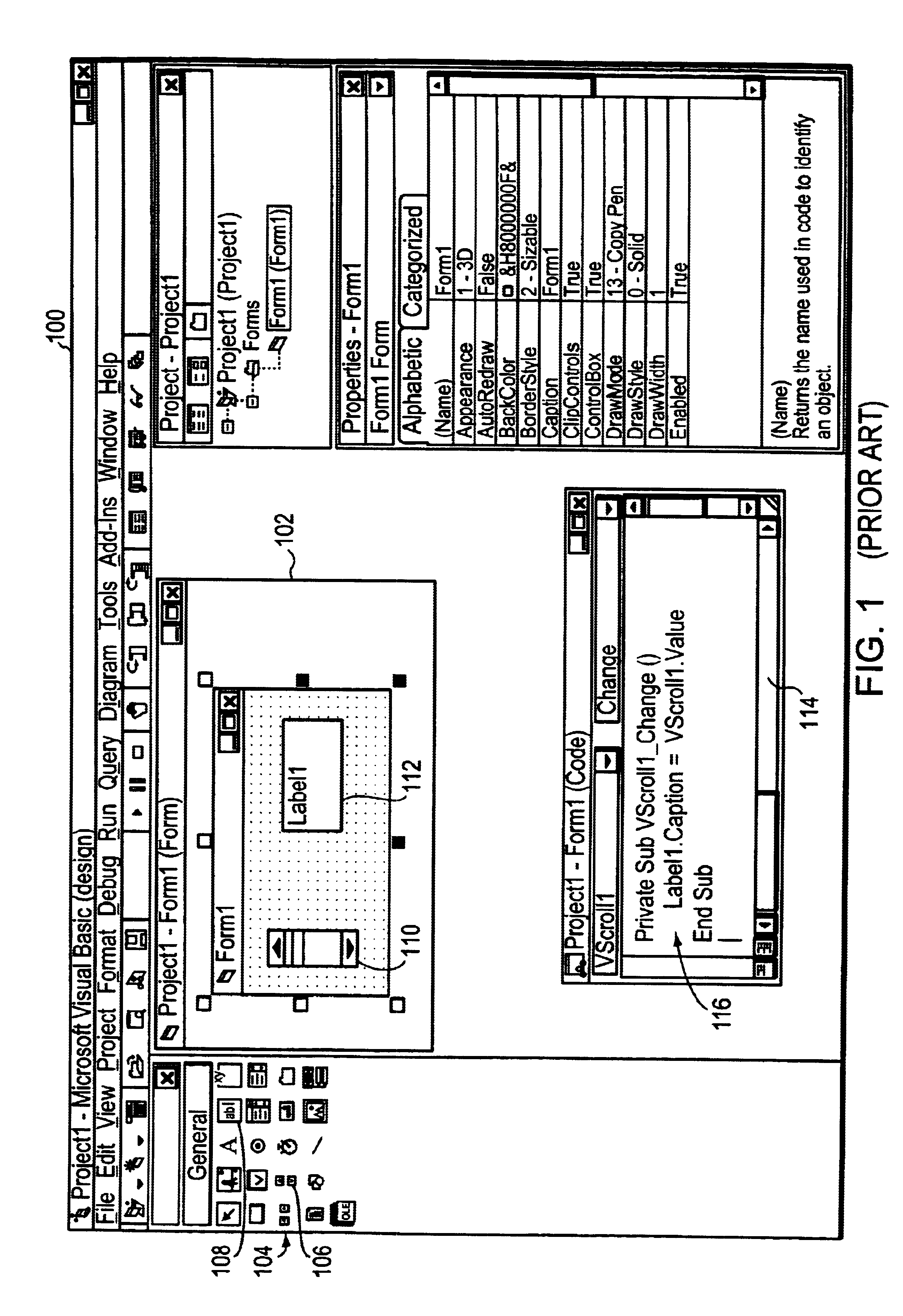
Furthermore, significant editing is often required to make even relatively minor adjustments to such user interface elements (e.g., moving, re-sizing, etc.).
Thus, the developer must learn and is limited by the syntax and keyword structures of Visual Basic.
Since this can take a significant amount time, it is often not done, unless the desired functionality is critical to the application program.
Accordingly, some application programs lack functionality that the developer would have preferred to include.
In addition, a graphical approach is not always the most expeditious way to represent or implement certain programs or subroutines.
For example, if the graphical programming method lacks a pre-defined solution for some desired functionality, then that functionality either cannot be implemented or its implementation would require such effort as to render the graphical programming method impractical as a programming tool.

Method used


Image

  • Program object for use in generating application programs
  • Program object for use in generating application programs
  • Program object for use in generating application programs

Examples


Embodiment Construction

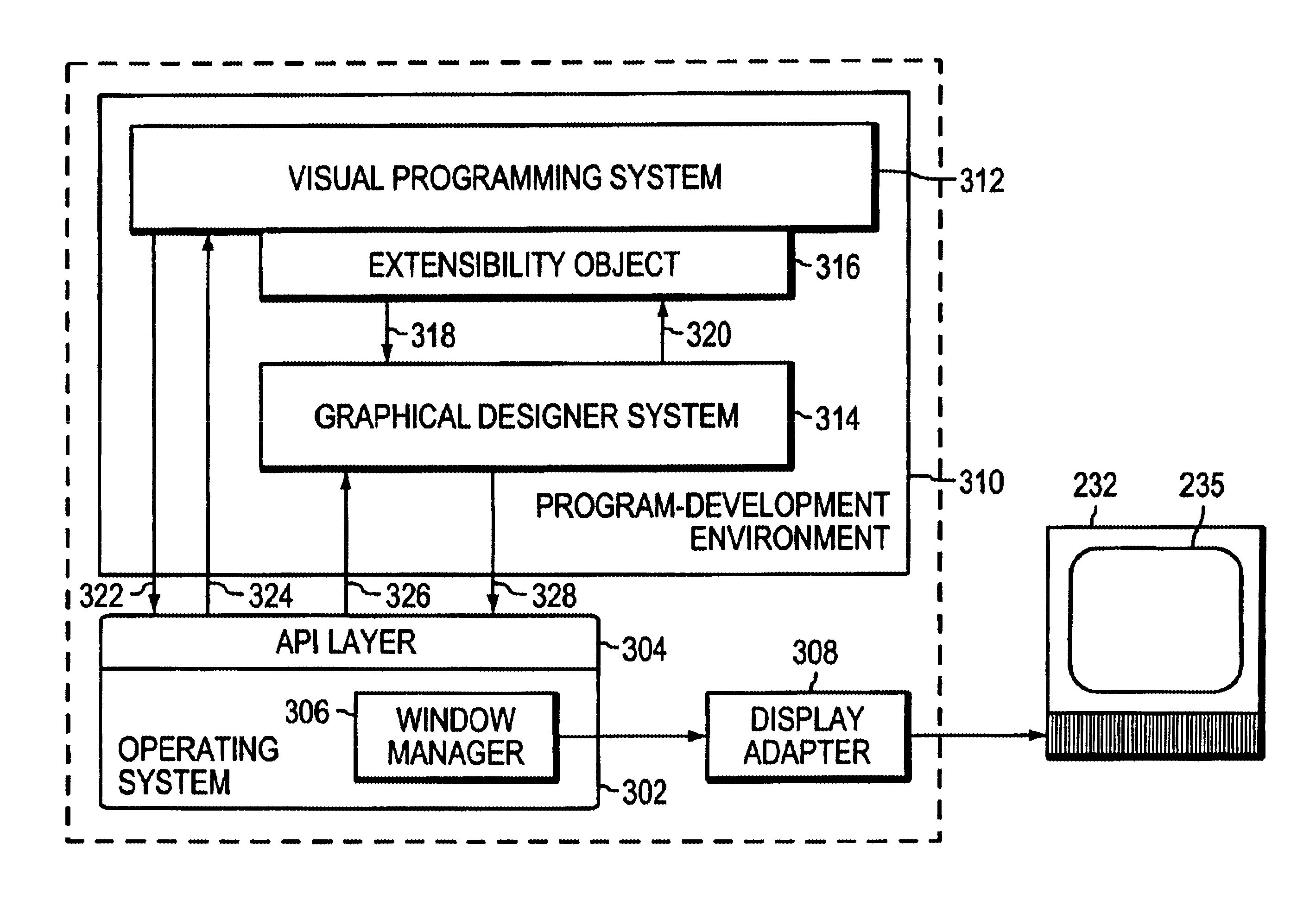
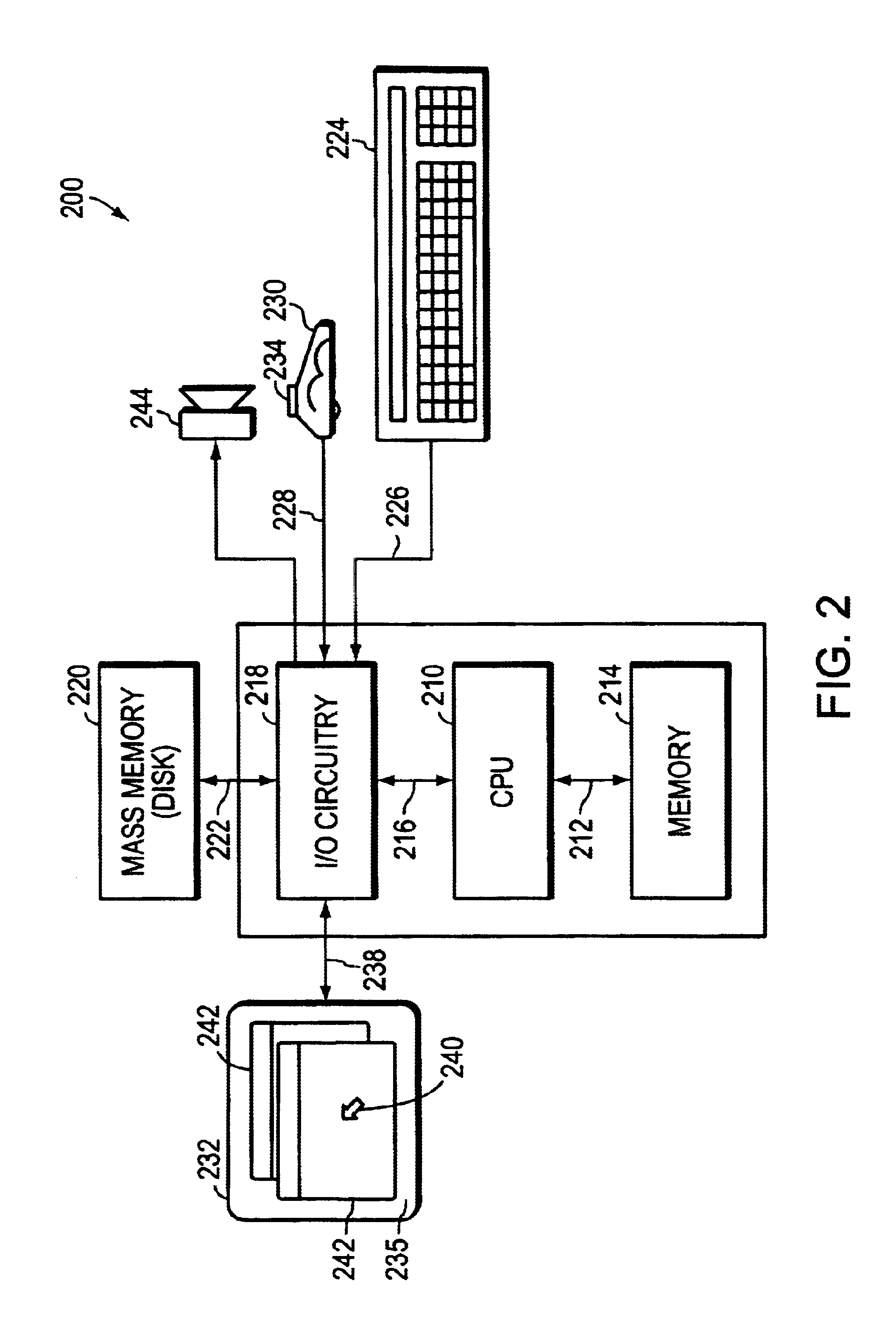
. 2 illustrates a computer system 200 comprising a central processing unit (CPU) 210 coupled between a memory 214 and input / output (I / O) circuitry 218 by bi-directional buses 212 and 216, respectively. The memory 214 typically comprises random access memory (RAM) for the volatile storage of information, including application programs and an operating system, and read only memory (ROM) for persistent storage of the computer's configuration and basic operating commands. As further described herein, the application programs and the operating system interact to control the operations of the CPU 210 and the computer system 200.

The I / O circuitry 218 may be connected to a mass memory storage unit 220, such as a disk drive, via bi-directional bus 222. In the typical system 200, the memory storage unit 220 contains instructions that can be read by the CPU 210 in order to configure system 200 to provide the program-development features of the present invention. Cursor / pointer control and inpu...


PUM


Abstract

The present invention relates to a program-development environment that allows developers to seamlessly switch between a visual programming paradigm and a textual programming paradigm, thereby permitting developers to choose the paradigm best suited for creating each aspect of the desired program. A graphical user interface (GUI) may be generated by the program-development environment, and displayed on the screen of a computer system. The GUI has several elements including a form window and a designer window. The form window is configured to receive one or more control objects selected by the developer, and the designer window is configured to display a symbolic representation of those control objects placed in the form window. According to the invention, these symbols can be linked together by the developer in the form of a data flow or block diagram that logically represents the flow of data and control information into, out of, and between the selected control objects, and that corresponds to the application program being generated. In response to such graphical inputs, the program-development environment generates event handler procedures or code for use with the application program being developed. The program-development environment additionally affords the developer, preferably through the use of a selectively displayable code window, the ability to provide or modify event handlers textually.

Description

FIELD OF THE INVENTIONThe present invention relates generally to the field of computer programming and, more specifically, to software development environments.BACKGROUND INFORMATIONTo generate a software program that can be executed or run by a computer, a software developer or programmer typically chooses a programming language, such as BASIC (Beginner's All-purpose Symbolic Instruction Code), Fortran, C, etc., and writes source code using the keywords, syntax, variable names, data structures, etc. defined by the selected programming language. Each programming language typically defines its own unique syntax and keywords for performing various functions. After the source code has been written, it is typically converted by a compiler into a machine readable format that can be understood by the computer (e.g., object code). If the developer used incorrect keywords or syntax, the source code cannot by compiled successfully.The source code is typically written with a text editor and o...

Claims


Application Information

Patent Timeline
IPC IPC(8): G06F9/44
CPCG06F8/34
Inventor BAILEY, BENDRIX L.PHILLIPS, CHRISTOPHER J.MORGANELLI, MICHAEL F.REILLY, GERARD M.
Owner NATIONAL INSTRUMENTS
Learn More