Method of balancing the bandwidth of a dual-mode filter

Inactive Publication Date: 2004-02-03
TELEFON AB LM ERICSSON (PUBL)
View PDF3 Cites 2 Cited by
  • Summary
  • Abstract
  • Description
  • Claims
  • Application Information

AI Technical Summary

Benefits of technology

The mentioned task is solved with the features of claim 1 in that the width of the ring line is narrowed at one or more sites of the ring resonator, at which the first of the two modes of the ring resonator has a current maximum, and at one or more sites of the ring resonator, at which the second mode has a current maximum. Owing to the fact that the resonance frequencies of the two modes existing in the ring resonator are balanced separately from each other, it is possible to vary the bandwidth of the filter.Advantageous modifications of the invention are apparent from the subclaims.The ring resonator has a line length that corresponds to its average operating wavelength or a multiple of it, so that the two resonance modes existing in the ring resonator have the same resonance frequencies.An additional strip line is preferably coupled to the ring resonator, via which the waves are coupled in and coupled out of the ring resonator. By changing the strip line width, the upper or lower filter flank can be made steeper, so that a narrower transition is produced between the stop-band region and the pass-band region of the filter on the correspondingly steepened flank. For steepening of the upper filter flank, the strip line can be narrowed at an interval of one-half wavelength, which corresponds to the average operating wavelength of the resonator, from the coupling site between the ring resonator and the strip line. It is then expedient to carry out narrowing on both sides of the coupling site, in each case at a spacing of a half-wavelength. Steepening of the lower filter flank is achieved by widening of the strip line at a spacing of a half-wavelength from the coupling site between the ring resonator and the strip line. The strip line is preferably widened on both sides of the coupling site, in each case at a spacing of a half-wavelength. The widening of the strip line can occur by bonding line pieces laterally onto the strip line.Removal of the line material for line narrowing can be carried out simply by means of a laser.

Problems solved by technology

Such notch filters can be produced in the form of ring resonators in strip line technology at very limited demands and cost effectively.

Method used


Image

  • Method of balancing the bandwidth of a dual-mode filter
  • Method of balancing the bandwidth of a dual-mode filter

Examples


Embodiment Construction

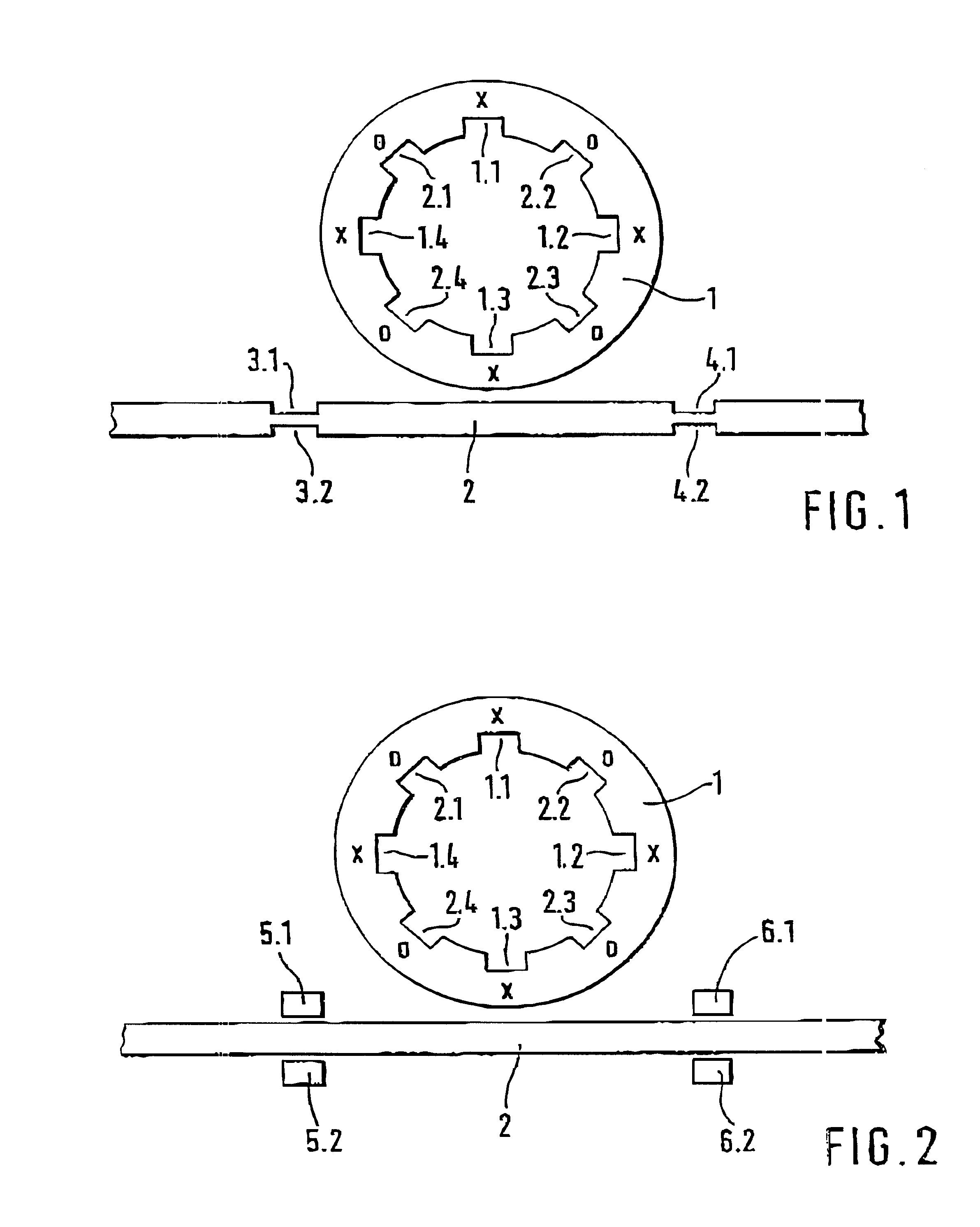
A ring resonator 1, designed as a strip line ring, is shown in FIG. 1. There are always two resonance modes in such a ring resonator. The ring resonator 1 has a length (which means the periphery of the circular center line of the ring resonator) of an even-number multiple of the average operating wavelength of the dual-mold filter produced by the ring resonator. The two modes are oriented orthogonal to each other; this means that the current maxima of one mode occur at the sites of the current minima of the other mode. The locations at which the first mode has current maxima are denoted x in the drawing on ring resonator 1, and the locations at which the second mode has current maxima are denoted o.

If a narrowing of the line width is now produced at the site of a current maximum of one mode on the strip line ring, the resonance frequency of this mode will be shifted to a lower frequency. A current minimum is situated with the other mode at the same site of the line narrowing, which ...


PUM


Abstract

A method of balancing the bandwidth of a dual-mode filter, consisting of a ring resonator produced by microstrip technology, removes strip material in one or more places on the ring resonator where the first of the two modes of the ring resonator has a maximum current intensity, and in one or more additional places on the ring resonator, where the second mode has a maximum current intensity.

Description

PRIOR ARTThe present invention concerns a method for balancing the bandwidth of a dual-mode filter, consisting of a ring resonator produced by strip line technology.A method for balancing the resonance frequency of a ring resonator is described in the older German Patent Application 198 21 382.4, in which line material is removed with a laser at one or more sites of the strip line ring until a desired resonance frequency is set. An additional strip line is coupled to the strip line ring, in which the resonance frequency of the filter can also be influenced by removing line material for narrowing of the conductor width. It follows from this older application that line material is removed at one or more sites of the strip line ring at which current maxima occur, in order to reduce the resonance frequency. Line material is removed on one or more sites of the strip line ring at which current minima occur, in order to increase the resonance frequency.Narrow-band notch filters that suppre...

Claims


Application Information

Patent Timeline
IPC IPC(8): H01P7/08
CPCH01P1/2039H01P7/082
Inventor SCHALLNER, MARTIN
Owner TELEFON AB LM ERICSSON (PUBL)
Why Eureka
Try Eureka