System and method for surveying utility outages

a utility and surveying technology, applied in non-electric variable control, process and machine control, instruments, etc., can solve the problems of utility providers not being able to quickly and easily detect and locate service outages, affecting electrical and telephony services, and utility lines being downed, so as to reduce the number of service calls and improve customer satisfaction

Inactive Publication Date: 2004-02-03
INTELLECTUAL VENTURES II
View PDF16 Cites 202 Cited by
  • Summary
  • Abstract
  • Description
  • Claims
  • Application Information

AI Technical Summary

Benefits of technology

Accordingly, it is desirable to provide methods and apparatus that allow a utility provider to quickly detect failures prior to service calls being made and to automatically locate and identify potential causes for the failures without physically searching the entire network. Similarly, it is desirable to provide methods and apparatus that will automatically notify customers of the current status of an outage thereby improving customer satisfaction and reducing the number of service calls.

Problems solved by technology

In today's environment, a utility provider is not able to quickly and easily detect and locate service outages.
For example, storms can cause downed utility lines, affecting electrical and telephony service to one or more customers on a street, in a neighborhood, or in a town.
Regardless of how the provider learns of the outage, it must still physically search for the exact location of the failure wasting both time and money.
In addition, customers often do not know the status of an outage and either flood the provider's service department with calls or are left wondering when service will be restored.

Method used


Image

  • System and method for surveying utility outages
  • System and method for surveying utility outages
  • System and method for surveying utility outages

Examples


first embodiment

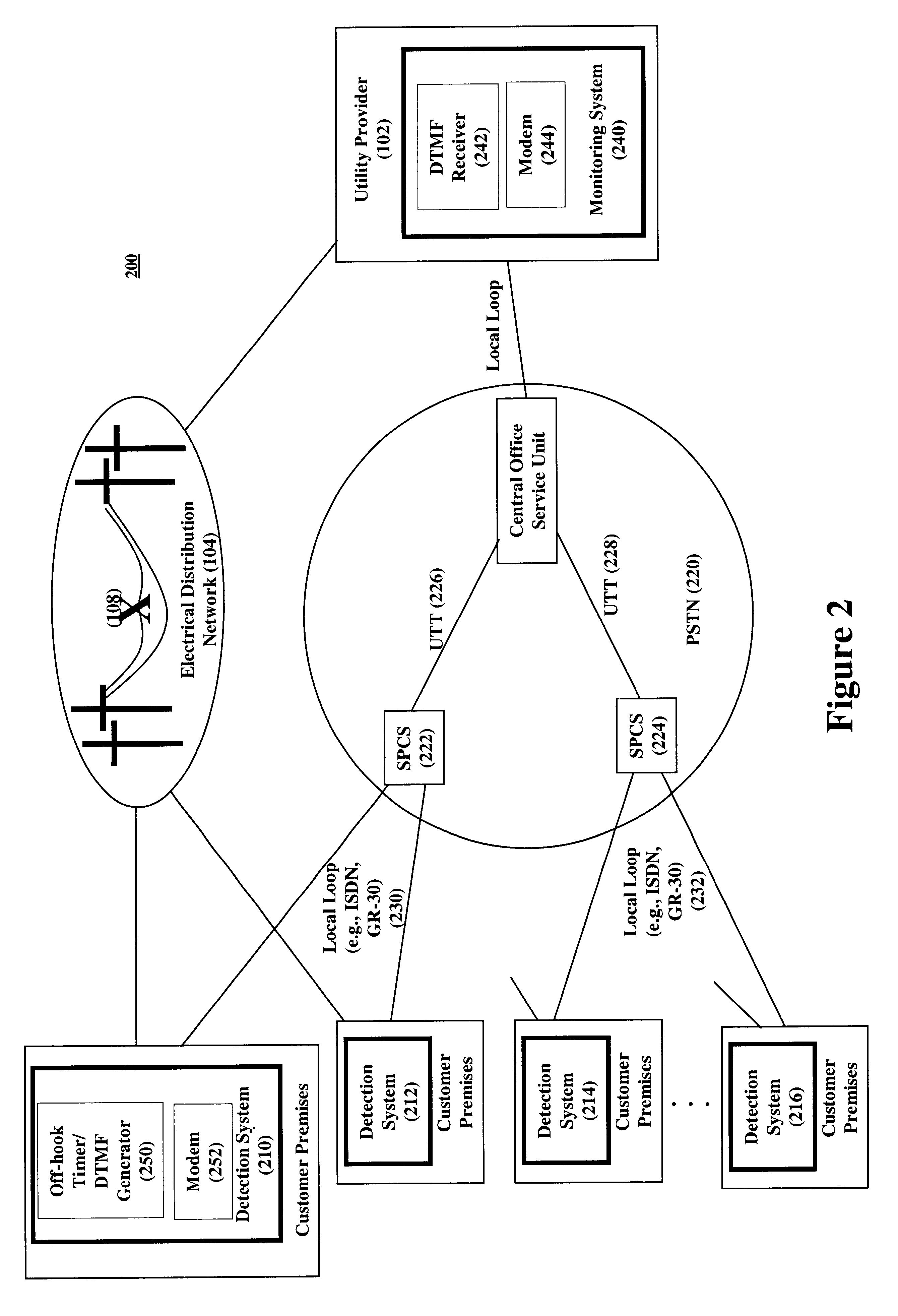
Reference will now be made to three specific communication networks over which our invention can be implemented. Again, the exact form of the communications network is not critical to our invention and one skilled in the art can readily implement our invention over different networks. FIG. 2 shows a first embodiment where the monitoring system communicates with the detection systems through PSTN 220, specifically, using the Utility Telemetry System (UTS). Here, PSTN addresses are assigned to the monitoring system and detection systems, which addresses are used to identify the systems and to establish connections. Under UTS, the monitoring system uses utility telemetry trunks (UTT) 226-228 to establish connections to stored program control switching systems (SPCS) 222-224 that serve the detection systems 210-216. Preferably, although not required, the SPCS's establish connections over the local loop 230-232 to the detection systems without using power-ringing (i.e., suppressed power ...

second embodiment

FIG. 3 shows a second embodiment where the monitoring system communicates with the detection systems through PSTN 320 as described in U.S. patent application Ser. No. 09 / 626,437 by Stanley Pietrowicz, filed Jul. 27, 2000. Under this communications method, a packet network 322, such as the CCS / SS7 signaling network, is used to convey the query, response, alerting, configuration, and status messages between the monitoring system 340 and detection systems 310-316. Similarly, the detection systems can establish, as an example, a separate modem connection through the transport network 324 to the monitoring system in order to send the status and response messages.

third embodiment

FIG. 4 shows a third embodiment where the monitoring system 440 communicates with the detection systems 410-416 through a packet network 422, such as that provided by an Internet service provider (ISP) and the Internet. Under this embodiment, the detection systems must have an "always-on" connection to the packet network, such as is provided by cable modem and xDSL modem access. Here, IP addresses can be assigned to the monitoring and detection systems, which addresses are used to identify the systems and to establish communications. All messages, for example, can be transmitted through the UDP protocol.

Although described with respect to electric utility providers, our invention is readily applicable to other applications. For example, if the communications network is other than the PSTN, the detection systems can monitor the presence / absence of telephony service and assist telephony service providers in detecting and locating telephony outages. Similarly, the system can monitor the...


PUM


Abstract

Utility failures are automatically detected and potential causes for these failures are automatically located and identified without having to physically search a utility provider's network. Detection systems capable of monitoring utility status are located at each, or a subset, of the customer premises serviced by a utility provider. A monitoring system, capable of correlating the geographical location of the detection systems with the geographical location of the equipment that comprises the utility provider's network, is located at a utility provider and interconnects with the detection systems through a communications network. The monitoring system queries the detection systems to determine utility status and to subsequently locate an outage and deduce a possible cause for the outage. Detection systems can also be configured to automatically contact the monitoring system to report utility status. The monitoring system is also capable of sending customer based information messages to the detection systems.

Description

BACKGROUND OF OUR INVENTION1. Field of the InventionOur invention relates generally to detecting and locating utility outages. More particularly, our invention relates to automatically detecting a utility outage within a utility provider's network and identifying and locating potential causes for the outage.2. Description of the BackgroundIn today's environment, a utility provider is not able to quickly and easily detect and locate service outages. For example, storms can cause downed utility lines, affecting electrical and telephony service to one or more customers on a street, in a neighborhood, or in a town. In other cases, an outage is specific to a particular customer, related to internal premises wiring. At times, the utility provider is able to detect the problem and at other times, the utility provider only learns of the outage once customers make service calls. Regardless of how the provider learns of the outage, it must still physically search for the exact location of the...

Claims


Application Information

Patent Timeline
Patent Type & Authority Patents(United States)
IPC IPC(8): H02J13/00
CPCH02J13/0024H02J13/0062H02J13/0072H02J13/0079Y04S40/122Y04S40/124Y04S40/125Y02E60/7823Y02E60/7838Y02E60/7846H02J13/00009H02J13/00018H02J13/00016H02J13/00028Y02E60/00Y04S40/121
Inventor PIETROWICZ, STANLEYLINK, FREDERICKALLPORT, DOUGLASROTHROCK, HAMILTON
Owner INTELLECTUAL VENTURES II
Why Eureka
Try Eureka