
Molecular fluorine laser system

a laser system and fluorine technology, applied in the direction of laser details, optical resonator shape and construction, electrical equipment, etc., can solve the problems of unreliable, competitive disadvantageous economic solution, occupying a lot of space,

Inactive Publication Date: 2004-02-10
LAMBDA PHYSIK
View PDF12 Cites 1 Cited by
  • Summary
  • Abstract
  • Description
  • Claims
  • Application Information

AI Technical Summary

Problems solved by technology

Use of the design set forth also involves synchronization of two laser systems, i.e., the oscillator and the amplifier, in parallel, which can be expensive, can tend to occupy a lot of space and may be unreliable under certain circumstances.
However, the design may also present, in some circumstances, a competitively disadvantageous economic solution relative to systems which would use the natural bandwidth of emission of the F.sub.2 laser for use with an imaging system having a catadioptric lens design.

Method used


Image

  • Molecular fluorine laser system
  • Molecular fluorine laser system
  • Molecular fluorine laser system

Examples


Embodiment Construction

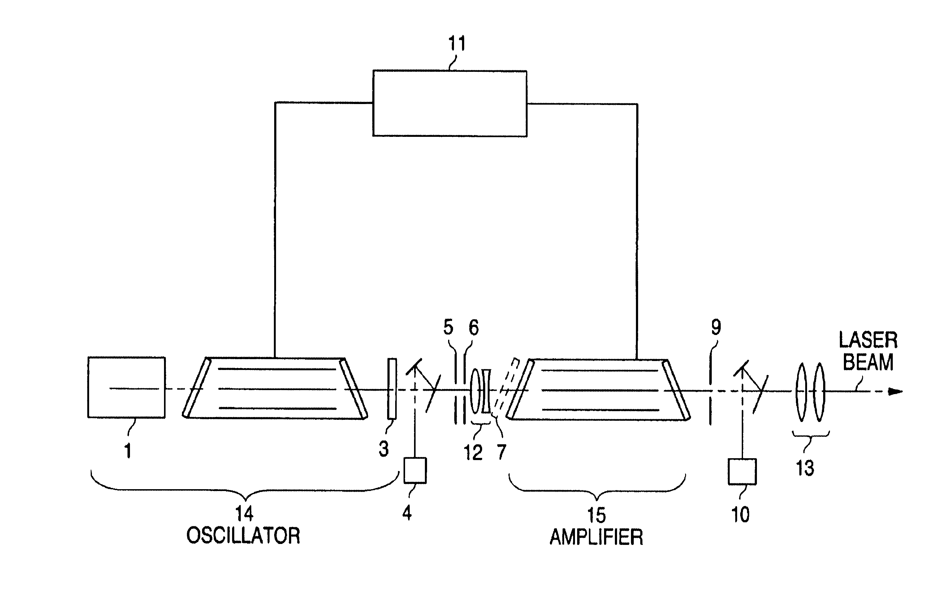
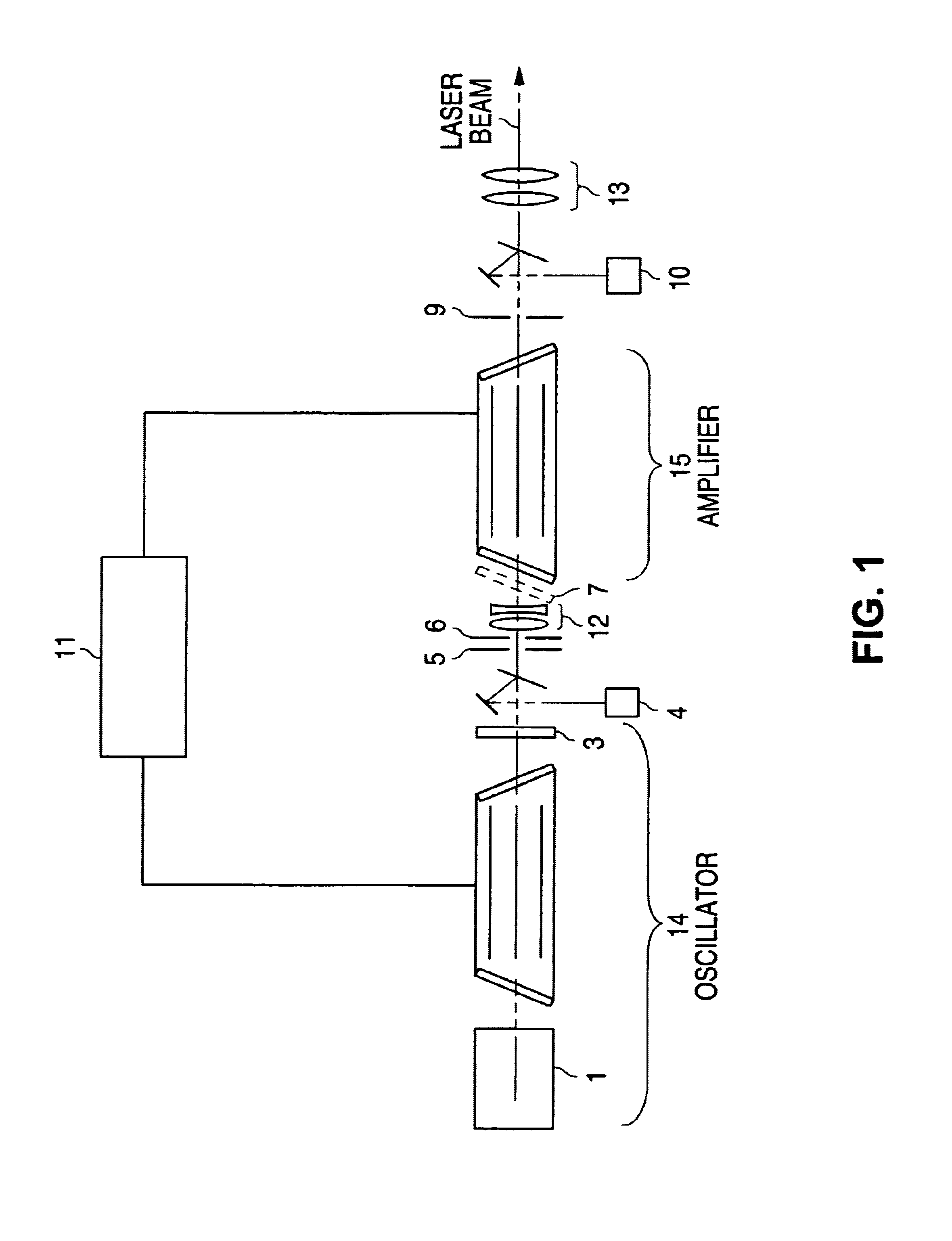
In FIG. 1 a preferred setup is shown. A molecular fluorine (F.sub.2)-laser oscillator (14) and power amplifier (15) are provided, wherein the master oscillator is a narrow linewidth 157 nm oscillator (see also U.S. patent applications Ser. Nos. 09 / 599,130 and 60 / 228,184, which are assigned to the same assignee as the present application and are hereby incorporated by reference). It is necessary to narrow the linewidth which is done by unit (1). Further this unit (1) may contain a suppression unit, because only the strongest line of the F.sub.2 -laser is of importance. The linewidth can be also varied by the He partial pressure and F.sub.2 concentration in the oscillator (14). A lower partial He pressure will effect a smaller linewidth (see also U.S. patent application Ser. No. 09 / 883,128 which are assigned to the same assignee as the present application and are hereby incorporated by reference).

The laser oscillator is followed by an output coupler (3) and an oscillator energy monito...


PUM


Abstract

A molecular fluorine laser includes a discharge chamber filled with a gas mixture including molecular fluorine and a buffer gas and not including a laser active rare gas, multiple electrodes within the discharge chamber defining a discharge region therebetween connected to a pulsed discharge circuit for applying discharge pulses to the electrodes for energizing the gas mixture, and a resonator including the discharge chamber for generating an oscillator laser beam at a wavelength around 157 nm and a bandwidth of less than 0.6 pm. The laser further includes a power amplifier for increasing the energy of the attenuated oscillator laser beam to a second predetermined energy for lithographic processing, a line-narrowing unit for reducing the bandwidth, a low intensity suppressor module to suppress the weaker lines of the F2-laser, and a synchronization unit to synchronize the oscillator and amplifier.

Description

The invention relates to molecular fluorine lasers emitting around 157 nm. The emitting molecular fluorine laser oscillator followed by an amplifier for increasing the energy of the emitted laser beam to a desired power for applications processing.DESCRIPTION OF THE RELATED ARTThe oscillator-amplifier design provides a laser beam at desired energies for application processing such as photolithography. Use of the design set forth also involves synchronization of two laser systems, i.e., the oscillator and the amplifier, in parallel, which can be expensive, can tend to occupy a lot of space and may be unreliable under certain circumstances. Preliminary experiments have shown that the oscillator-amplifier stage can provide an advantageous 157 nm laser beam for application processing. However, the design may also present, in some circumstances, a competitively disadvantageous economic solution relative to systems which would use the natural bandwidth of emission of the F.sub.2 laser for...

Claims


Application Information

Patent Timeline
Patent Type & Authority Patents(United States)
IPC IPC(8): H01S3/14H01S3/223H01S3/225H01S3/08H01S3/23
CPCH01S3/08H01S3/225H01S3/2366H01S3/2308
Inventor VOGLER, KLAUS WOLFGANGGOVORKOV, SERGEI V.HUA, GONGXUEVOSS, FRANKBERGMANN, ELKO
Owner LAMBDA PHYSIK
Learn More