Optical fiber circuit

a fiber optic circuit and optical fiber technology, applied in the field of optical circuits, can solve the problems of significant differences in the transmission time of port-to-port between the various ports, increase in the fiber layout, and general inacceptability, so as to reduce the incidence of fiber stacking, avoid fiber stacking, and minimize skew

Inactive Publication Date: 2004-02-10
TE CONNECTIVITY CORP
View PDF5 Cites 53 Cited by
  • Summary
  • Abstract
  • Description
  • Claims
  • Application Information

AI Technical Summary

Benefits of technology

The present invention provides for an optical circuit that minimizes skew but avoids fiber stacking by using an asymmetrical fiber arrangement for interconnecting the input and output nodes. The applicant has found that by asymmetrically arranging the fi

Problems solved by technology

The applicants have found that as the number of input and output ports (or nodes) increases in an optical fiber circuit, the problems facing the fiber layout increase as well.
If this differential becomes large, it can result in a significant difference in the port-to-port transmission time among the various ports.
This is generally unacceptable.
Applicants have identified a number of problems associated with the stacking of multiple fibers.
This introduces optical losses and can compromise the integrity of the optical transmission path in general.
Aside

Method used


Image

  • Optical fiber circuit
  • Optical fiber circuit

Examples


Embodiment Construction

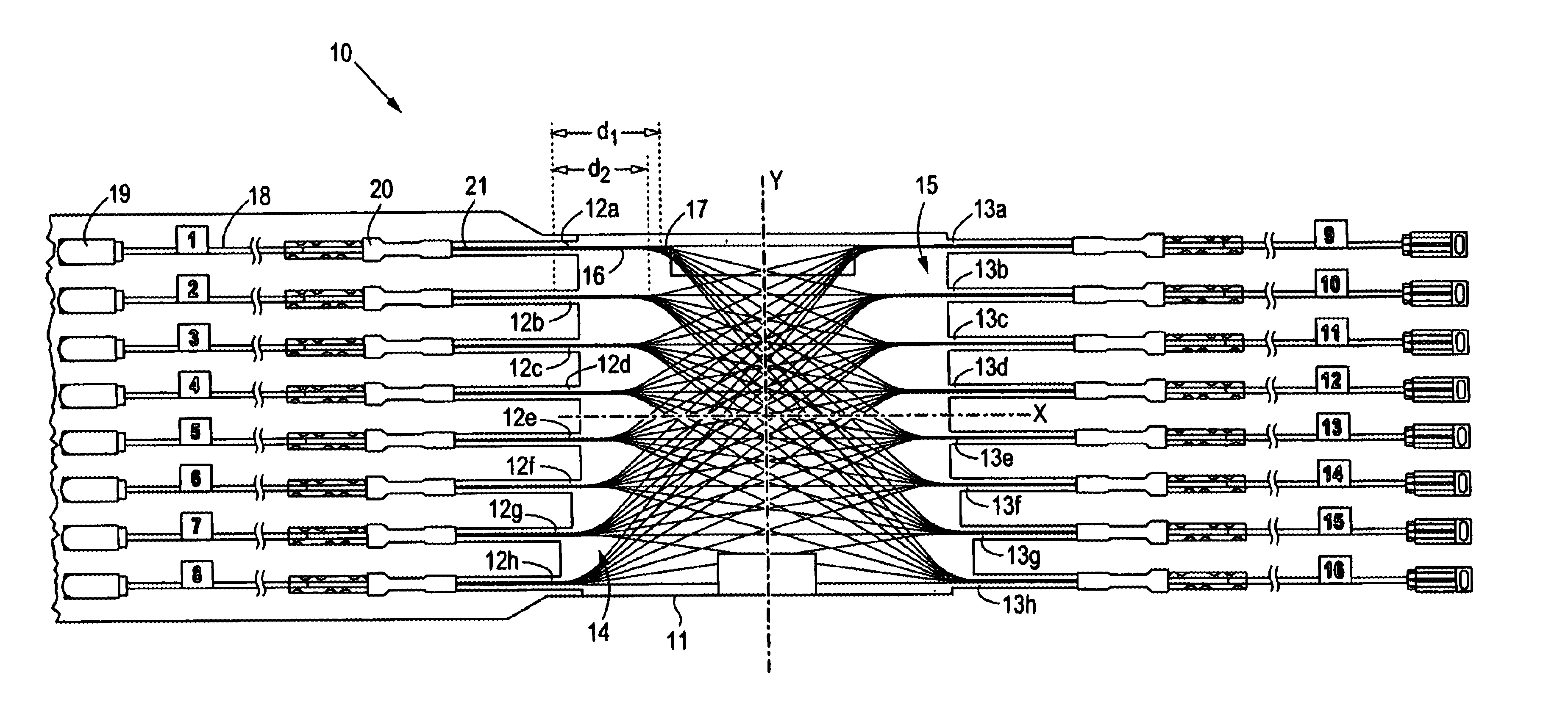
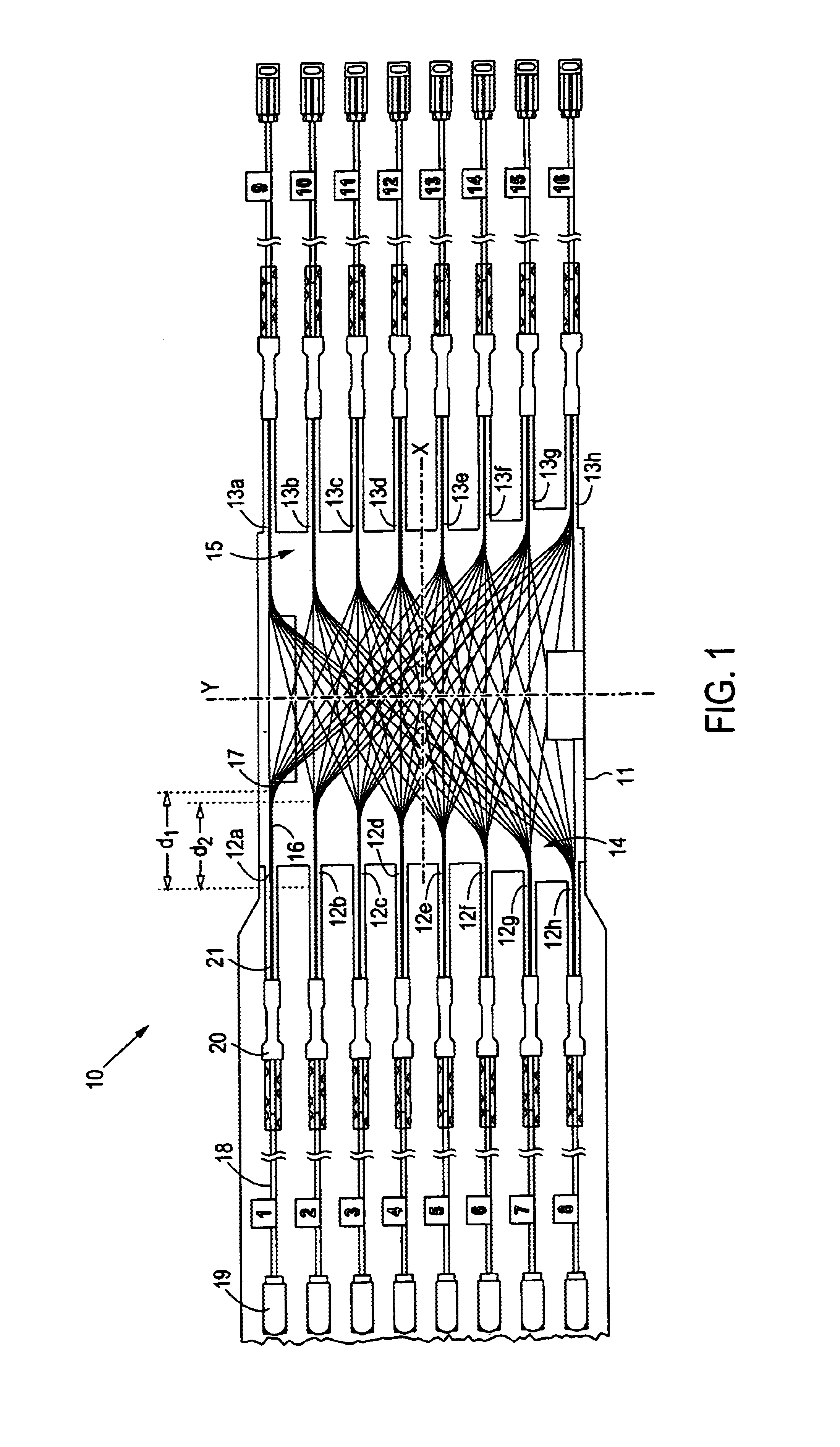
Referring to FIG. 1, a preferred embodiment of the optical circuit 10 of present intention is shown. The optical circuit comprises a body 11 having an x and y axis and two sides 14, 15 substantially parallel to the y-axis and separated along the x-axis. A plurality of first ports 12a-h is disposed along one side 14, and a plurality of second ports 13a-h is disposed along the other side 15. Each port comprises a number of substantially paralleled fibers. These parallel fibers are indicated as 16 for port 12a.

The fibers of the ports are arranged to interconnect the first and second ports along straight, hence, diagonal lines. In a preferred embodiment, the fibers of a given second port, for example port 13a, comprise a fiber from each of the first ports 12a-h. The fibers interconnecting the first and second ports are arranged asymmetrically about at least one of the x or y axes. In the embodiment shown in FIG. 1, the fibers are asymmetrical about the x-axis. It should be understood, h...


PUM


Abstract

An optical circuit comprises: (a) a body having an x and y axis and two sides substantially parallel to the y-axis and separated along the x-axis; (b) a plurality of first ports along one of the two sides, each first port comprising a number of substantially paralleled fibers; and (c) a plurality of second ports along the other of the two sides, each second port comprising a number of substantially parallel fibers. The ports are interconnected with the fibers such that (i) the fibers of a given second port comprise a fiber from each of the first ports, and (ii) the fibers interconnecting the first and second ports are arranged asymmetrically about at least one of the x or y axes.

Description

The present invention related generally to optical circuits, and, more specifically, to an optical circuit in which fibers interconnect input and output ports.The use of optical fiber circuits to manage the fibers between optical connections has increased dramatically in recent years. The primary reason for this dramatic increase is the constant desire to increase the density of optical connections. In other words, there is a strong impetus to increase the number of fibers that can be optically connected in a given space. As the density of the optical connections increases, the need to manage the ganglia of fibers associated therewith increases in kind. As used herein, the term "optical fiber circuit" refers broadly to an arrangement of fibers that interconnects one set of ports with another set of ports. The arrangement of fibers is fixed to some medium to prevent its movement. The terms "input port" and "output port" are used herein for illustrative purposes to provide a distincti...

Claims


Application Information

Patent Timeline
IPC IPC(8): G02B6/43
CPCG02B6/43
Inventor RIETVELD, WILLY
Owner TE CONNECTIVITY CORP
Why Eureka
Try Eureka