Method of mounting a coil unit for use as an image heating apparatus

a heating apparatus and coil technology, applied in the direction of electric/magnetic/electromagnetic heating, magnetic bodies, instruments, etc., can solve the problems of reducing the manufacturing efficiency of exciter coils and increasing the production cost of exciter coils

Inactive Publication Date: 2004-02-17
CANON KK
View PDF10 Cites 34 Cited by
  • Summary
  • Abstract
  • Description
  • Claims
  • Application Information

AI Technical Summary

Benefits of technology

Another object of the present invention is to provide an image heating apparatus in which the temperature of said rotational member does not become lower across its longitudinal end portions that its central portion.

Problems solved by technology

However, such disposition of the exciter coil made the exciter coil complicated in shape, which reduced the manufacturing efficiency for the exciter coil, increasing therefore the production cost for the exciter coil, which was a problem.

Method used


Image

  • Method of mounting a coil unit for use as an image heating apparatus
  • Method of mounting a coil unit for use as an image heating apparatus
  • Method of mounting a coil unit for use as an image heating apparatus

Examples


Embodiment Construction

Hereinafter, the preferred embodiments of the present invention will be described with reference to the appended drawings.

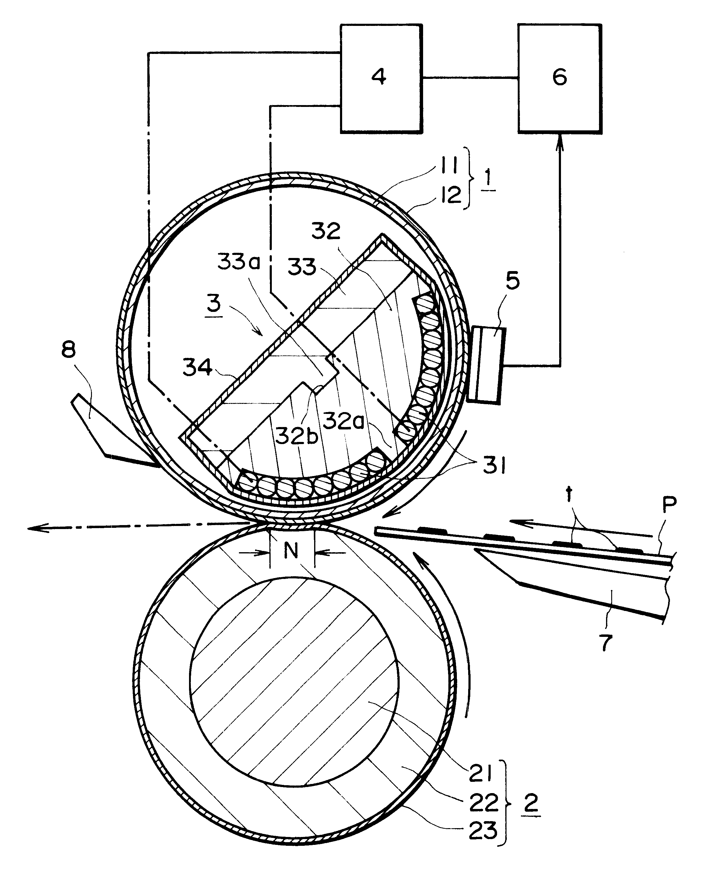
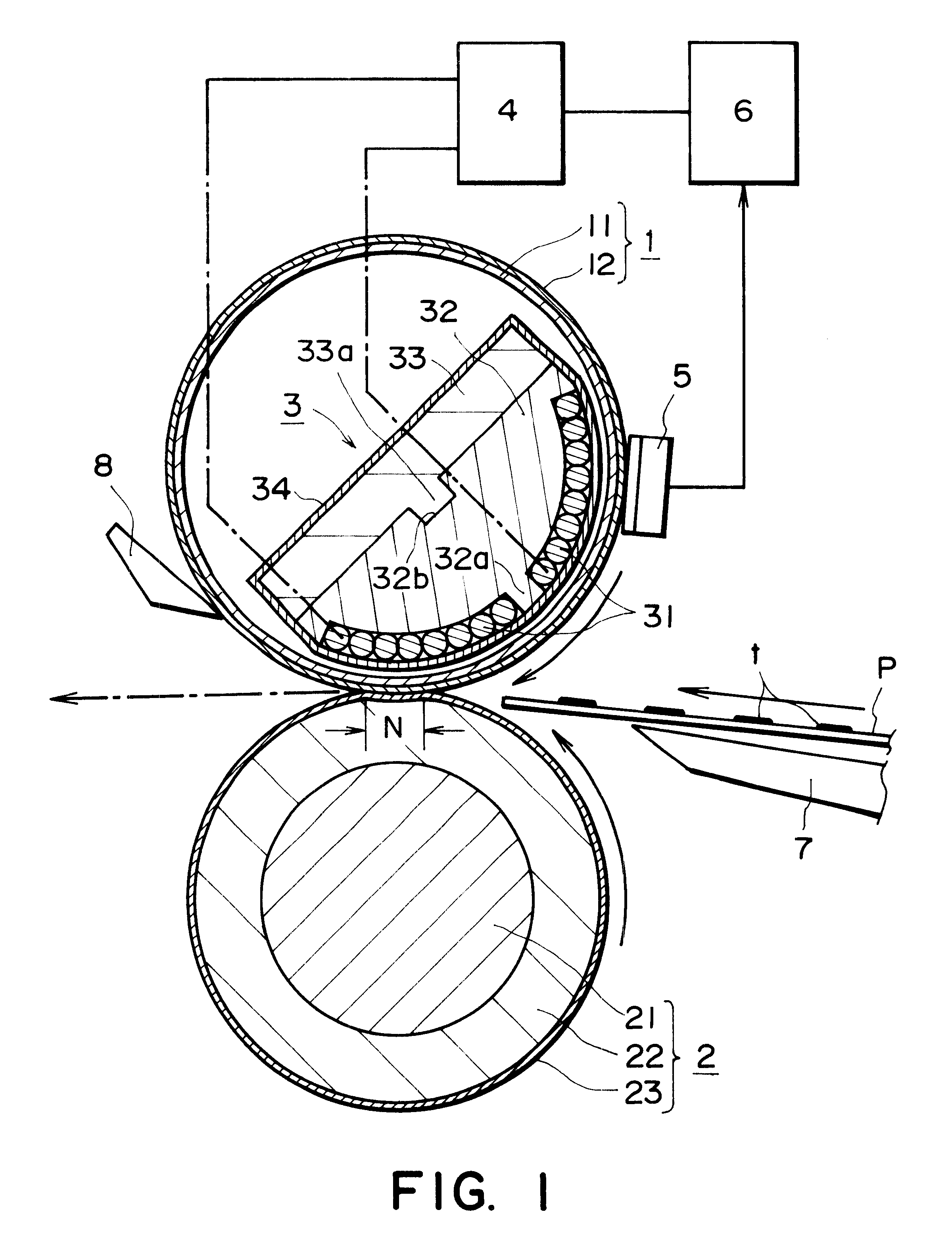
FIG. 6 is a schematic vertical sectional view of an example of an image forming apparatus equipped with an induction type heating apparatus as an apparatus for thermally fixing an image, and depicts the general structure of the image forming apparatus. This image forming apparatus is a laser beam printer which uses a transfer type electrophotographic process. First, this apparatus will be described.

A referential character 41 designates a rotational electrophotographic photosensitive member (hereinafter, photosensitive drum) in the form of a cylindrical drum, which is rotatively driven in the clockwise direction at a predetermined peripheral velocity (process speed).

As the photosensitive drum 41 is rotated, it is uniformly charged to predetermined polarity and potential level by a charge roller 42 as a charging apparatus.

Then, the photosensitive drum 41 is exposed...


PUM

PropertyMeasurementUnit
diameteraaaaaaaaaa
diameteraaaaaaaaaa
thickaaaaaaaaaa

Abstract

A method of mounting a coil inside a rotatable member for heating an image, includes a winding step of winding wire into a coil in a plane to provide a planer coil; and a mounting step of bending the planer coil and mounting it to a supporting member.

Description

FIELD OF THE INVENTION AND RELATED ARTThe present invention relates to an image heating apparatus employed in an image forming apparatus such as a copying machine or a printer. In particular, it relates to a method for assembling a coil to be employed in an image heating apparatus.In image forming apparatuses such as copying machines or printers, a toner image (image formed of developer (toner) comprising resin, magnetic material, coloring material, and the like) is formed through one of image formation processes, for example, an electrophotographic image formation process, or an electrostatic recording process. In some image forming apparatuses, a toner image is directly formed on recording medium, and in others, it is indirectly formed on recording medium, that is, it is formed on a primary image bearer and then, is transferred onto recording medium. The thus formed toner image on recording medium is thermally fixed to recording medium with the use of a fixing apparatus. Although ...

Claims


Application Information

Patent Timeline
Patent Type & Authority Patents(United States)
IPC IPC(8): G03G15/20H05B6/14
CPCG03G15/2053H05B6/145Y10T29/49117Y10T29/49071Y10T29/49012
Inventor HAYASHI, YASUHIROOHTA, TOMOICHIROUFUJITA, TAKASHIMAEYAMA, RYUICHIROU
Owner CANON KK
Why Eureka
Try Eureka