
Fuel injection quantity control system for engine

a technology of quantity control system and injection quantity control, which is applied in the direction of electric control, combustion engines, machines/engines, etc., can solve the problems of pilot injection being unable to achieve the effect of pilot injection, aging deterioration, and may vanish or become excessive,

Inactive Publication Date: 2004-02-24
DENSO CORP
View PDF4 Cites 56 Cited by
  • Summary
  • Abstract
  • Description
  • Claims
  • Application Information

AI Technical Summary

Benefits of technology

This approach prevents excessive correction values, reducing combustion noise, engine vibration, and exhaust emission while maintaining optimal engine performance by accurately accounting for injector individual differences and aging deterioration.

Problems solved by technology

Therefore, there is a possibility that the pilot injection may vanish or become excessive due to an injector individual difference, variation in the actual injection quantity with respect to fuel injection command pulse period (inter-cylinder injection quantity variation), or a deterioration in performance (function) of the injector with an aging change or the like (injector aging deterioration).
As a result, an effect of the pilot injection cannot be achieved sufficiently.
As a result, the excessive correction value obtained through the erroneous learning will pose problems of deterioration in the combustion noise, engine vibration, emission or the like.
As a result, the engine performance deterioration is inhibited.

Method used


Image

  • Fuel injection quantity control system for engine
  • Fuel injection quantity control system for engine
  • Fuel injection quantity control system for engine

Examples


first embodiment

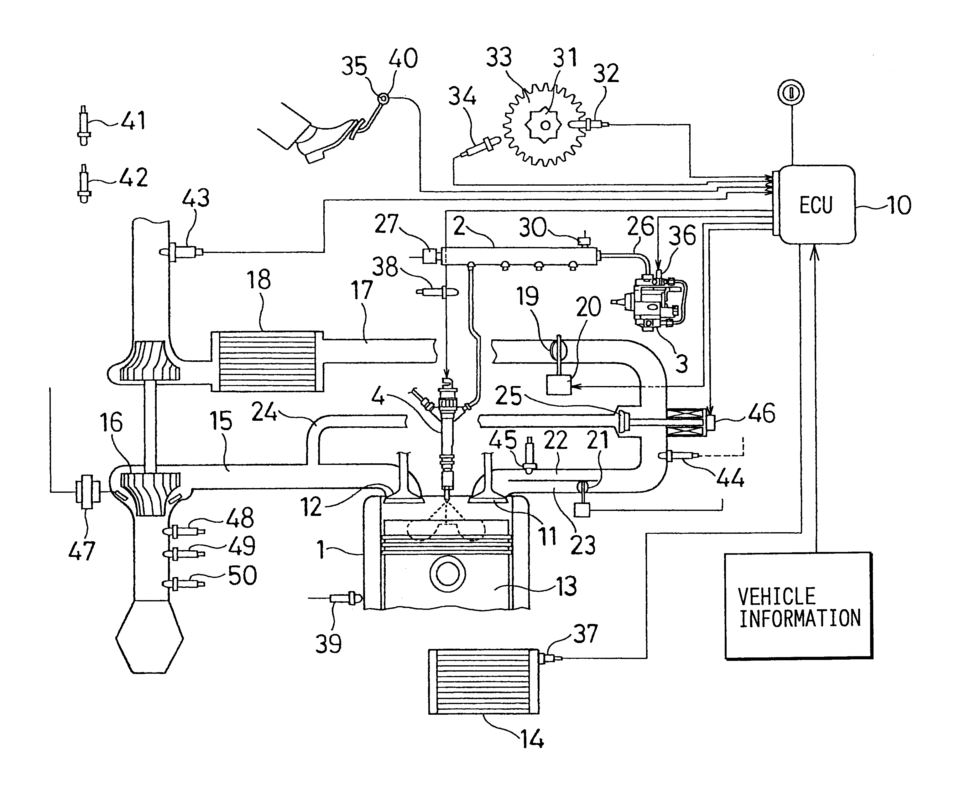
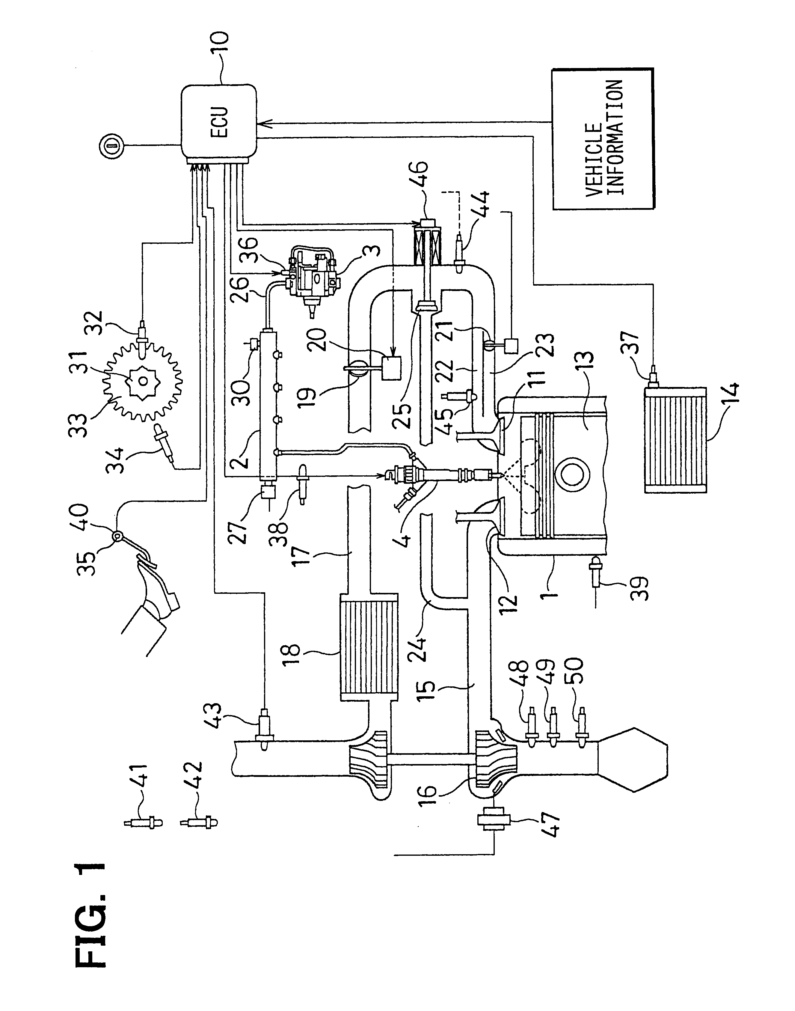
Referring to FIG. 1, a common-rail type fuel injection system according to the first embodiment is illustrated.

The common-rail type fuel injection system in the first embodiment includes a common rail 2, i.e., an accumulator for storing a high-pressure fuel pressurized at a high pressure corresponding to a fuel injection pressure at which the fuel is injected into cylinders of an internal combustion engine, such as a four-cylinder diesel engine (hereinafter referred to simply as "engine"), a fuel supply pump 3, i.e., a fuel feed pump, for supplying the fuel under pressure into the common rail 2, a plurality of injectors 4 (four injectors in the embodiment) for injecting the high-pressure fuel accumulated in the common rail 2 into the cylinders of the engine 1, and an electronic control unit (hereinafter abbreviated to "ECU") 10 for electronically controlling the fuel supply pump 3 and the plurality of injectors 4.

The engine 1 is a four-stroke cycle four-cylinder engine provided with...

second embodiment

Next, a method of pilot learning control according to the second embodiment will be explained based on FIG. 14.

In the second embodiment, even if Q1 as the final injection quantity correction value and Q2 as the increase quantity of the engine-demanded injection quantity due to the engine load factor are not calculated, the first learning value corresponding to the target fuel pressure PFIN of, for instance, A MPa is read from the memory. Then, Qb for K times injections is calculated based on Expression (23) shown below in Step S31.

(QISC+QFCCB)=Q1.times.K+Q2Qb Expression (23)

where Q1 designates the injector individual difference, the inter-cylinder injection quantity variation and the injector aging deterioration quantity, Q2 designates the variation in the engine-demanded injection quantity, and K designates the injection frequency per combustion in the multi-injection.

Then, the second learning value corresponding to the target fuel pressure PFIN of A MPa is read from the memory and...


PUM


Abstract

An injection quantity control system for an internal combustion engine stores a value Qb, which is a sum of an FCCB correction value and an ISC correction value corresponding to an injection frequency of K times per combustion in multi-injection in an idling stabile state of the engine. The system stores a value Qc, which is a sum of the FCCB correction value and the ISC correction value corresponding to the injection frequency of N times. Based on a difference between the values Qb and Qc, a final learning value (Q1 / K or Q1 / N) is calculated. Thus, an injector individual difference, an inter-cylinder injection quantity variation, and an injector aging deterioration quantity can be discriminated from an increase in an engine-demanded injection quantity due to an engine load factor.

Description

1. Field of the InventionThe present invention relates to an injection quantity control system for an internal combustion engine for correcting an injector individual difference, an inter-cylinder injection quantity variation and an injector aging deterioration quantity in an injection quantity correction value for each cylinder of the engine or in an energization period correction value for an electromagnetic valve of an injector. Specifically, the present invention relates to a pilot injection quantity control system capable of performing a small quantity of pilot injection at least once before main injection by driving the electromagnetic valve of the injector by a plurality of times in compression stroke and expansion stroke of the engine.2. Description of Related ArtConventionally, there is a known common rail type fuel injection system for injecting high-pressure fuel, which is accumulated in a common rail, into each cylinder of a multi-cylinder diesel engine. In the common ra...

Claims


Application Information

Patent Timeline
Patent Type & Authority Patents(United States)
IPC IPC(8): F02D41/14F02D41/08F02D41/22F02D41/00F02D41/40F02D41/24F02D41/34F02D45/00F02D41/30F02D41/38
CPCF02D41/0085F02D41/08F02D41/221F02D41/247F02D41/248F02D41/402F02D41/1498F02D2200/0602F02D2200/1015Y02T10/44Y02T10/40F02D41/30
Inventor KAWAGUCHI, YOSHIOTAKEUCHI, KATSUHIKO
Owner DENSO CORP
Learn More