Fastening a CMC combustion chamber in a turbomachine using brazed tabs

a combustion chamber and turbomachine technology, applied in the direction of machines/engines, mechanical equipment, light and heating apparatus, etc., can solve the problems of inconvenient installation, metal chambers that are completely unsuitable, and the coefficient of thermal expansion of metals and composites is very different, so as to save mass, facilitate installation, and maintain the initial structure of the chamber

Inactive Publication Date: 2004-03-23
SN DETUDE & DE CONSTR DE MOTEURS DAVIATION S N E C M A
View PDF7 Cites 58 Cited by
  • Summary
  • Abstract
  • Description
  • Claims
  • Application Information

AI Technical Summary

Benefits of technology

The present invention mitigates those drawbacks by proposing a mounting for the combustion chamber in the casings with the ability to absorb the displacements induced by the various coefficients of expansion of those parts. An object of the invention is thus to propose a mounting which makes the best use of the existing characteristics of the combustion chamber.
These objects are achieved by a turbomachine comprising inner and outer annular shells of metal material containing in a gas flow direction F: a fuel injector assembly, an annular combustion chamber of composite material and having a longitudinal axis, and an annular nozzle of metal material and forming the fixed-blade inlet stage of a high pressure turbine, wherein said composite material combustion chamber is held in position between said inner and outer metal annular shells by a plurality of flexible tongues, first ends of said tongues being interconnected by a metal ring fixed securely to each of said inner and outer metal annular shells by first fixing means, and second ends being fixed by second fixing means to a ring of composite material fixed securely to said composite material combustion chamber, the flexibility of said fixing tongues allowing expansion to take place freely in a radial direction at high temperatures between said composite material combustion chamber and said metal annular shells.
With this particular structure for the fixed connection, the various kinds of wear due to contact corrosion in prior art systems can be avoided. The use of a ring made of composite material to provide sealing of the stream also makes it possible to keep the initial structure of the chamber intact. In addition, the presence of flexible metal tongues replacing the traditional flanges gives rise to a saving in mass that is particularly appreciable. In addition to being flexible, these tongues make it easy to accommodate the expansion difference that appears at high temperatures between metal parts and composite parts (by accommodating the displacements due to expansion) while still ensuring that the combustion chamber is properly held and well centered in the annular shell.

Problems solved by technology

Nevertheless, under certain particular conditions of use implementing particularly high combustion temperatures, a metal chamber turns out to be completely unsuitable from a thermal point of view and it is necessary to make use of a chamber that is based on high temperature composite materials of the CMC type.
However, difficulties of implementation and materials costs mean that such materials are generally restricted to being used for the composite chamber itself, with the high pressure turbine inlet nozzle and the inner and outer shells of the chamber then still being made more conventionally out of metal materials.
Unfortunately, metals and composites have coefficients of thermal expansion that are very different.
This gives rise to particularly awkward problems of connection with the inner and outer shells of the combustion chamber and of interface at the nozzle at the inlet to the high pressure turbine.

Method used


Image

  • Fastening a CMC combustion chamber in a turbomachine using brazed tabs
  • Fastening a CMC combustion chamber in a turbomachine using brazed tabs
  • Fastening a CMC combustion chamber in a turbomachine using brazed tabs

Examples


Embodiment Construction

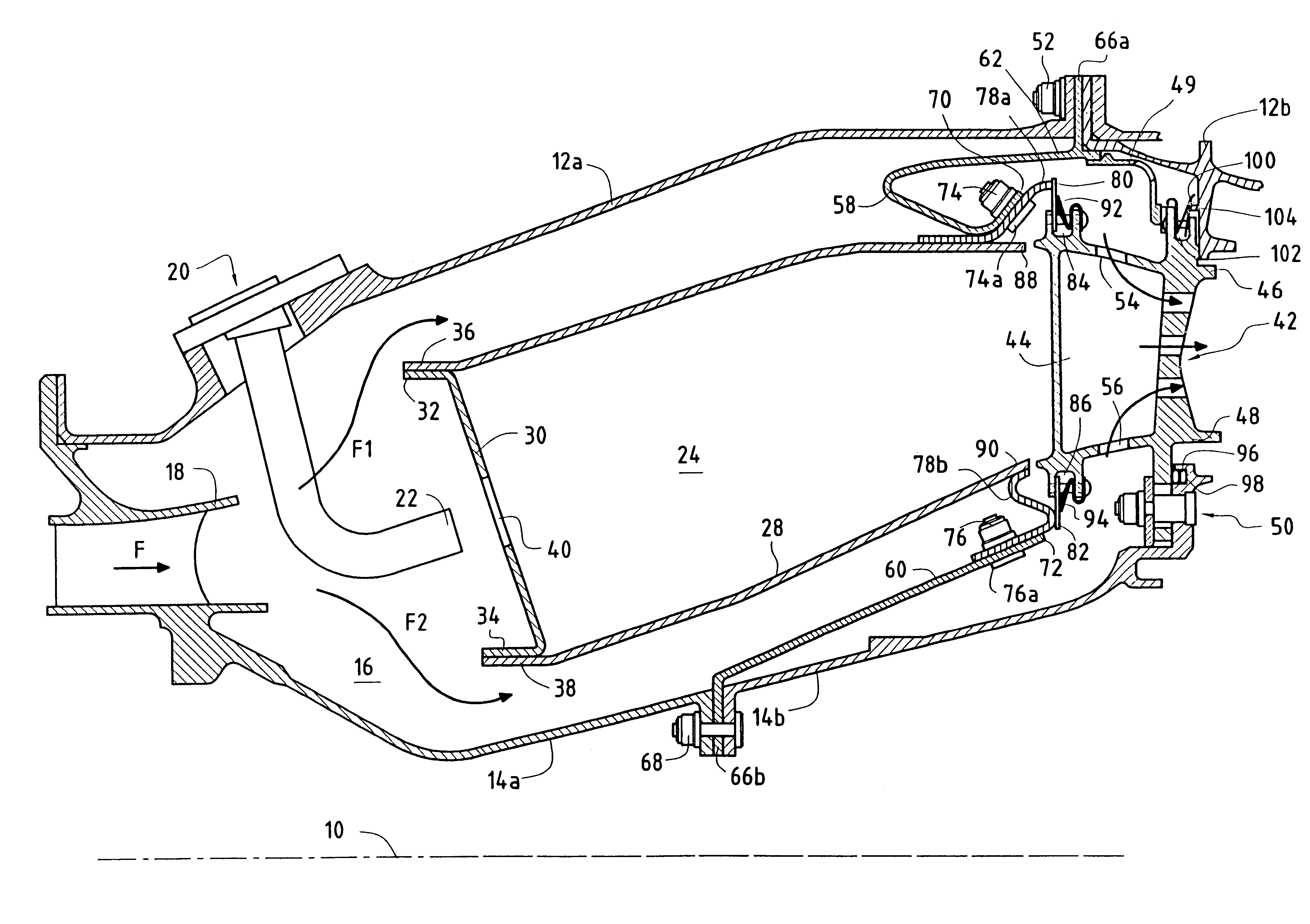
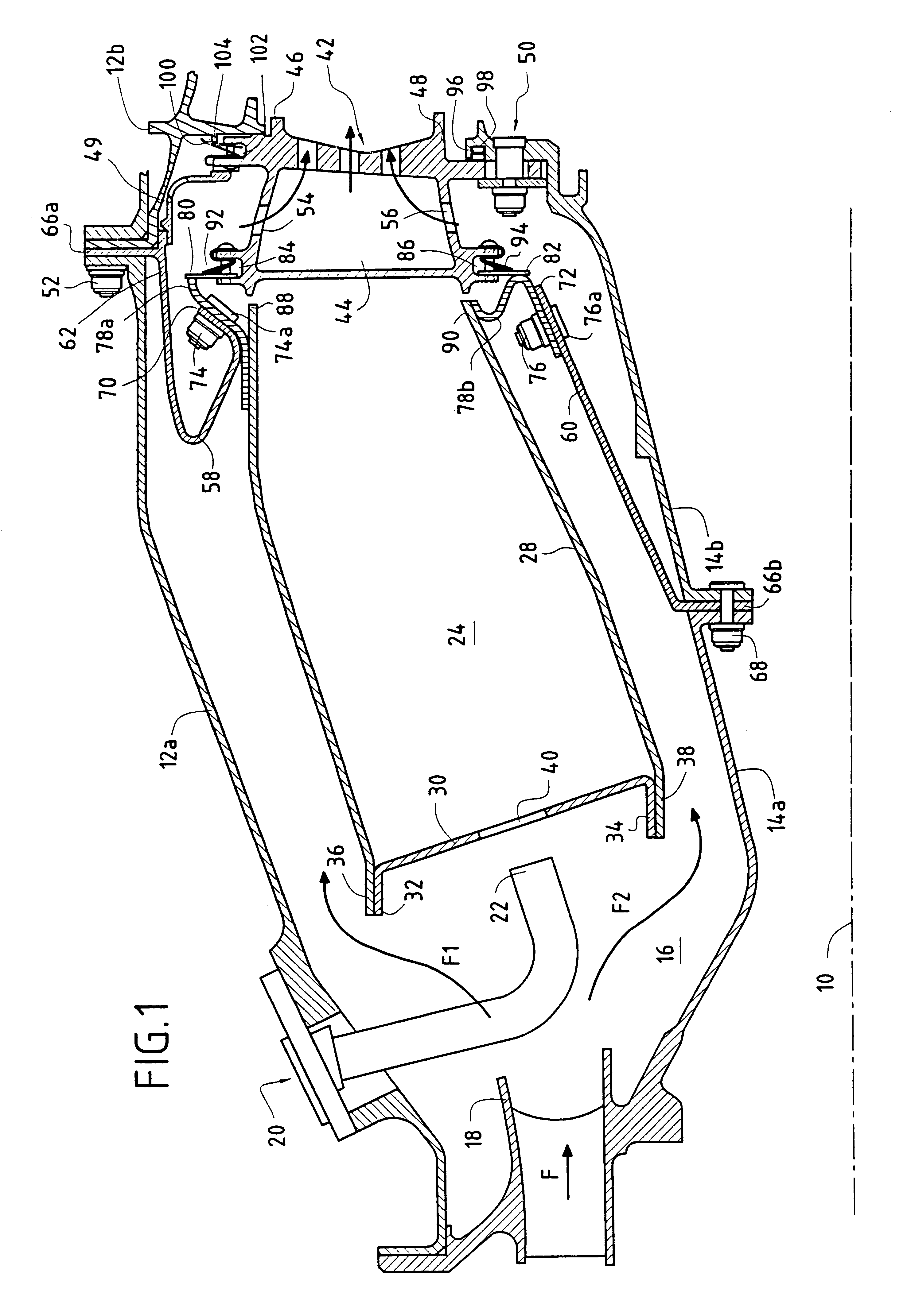
FIG. 1 is an axial half-section view of a central portion of a turbojet or a turboprop (with the term "turbomachine" being used generically in the description below) and comprising:

an outer annular shell (or outer casing) made up of two portions 12a and 12b of metal material, having a longitudinal axis 10;

an inner annular shell (or inner casing) that is coaxial therewith and likewise comprises two portions 14a and 14b, also made of metal material; and

an annular space 16 extending between the two shells 12a, 12b and 14a, 14b for receiving compressed oxidizer, generally air, coming from an upstream compressor (not shown) of the turbomachine via an annular diffuser duct 18 defining a general flow F of gas.

In the gas flow direction, this space 16 comprises firstly an injection assembly formed by a plurality of injection systems 20 that are regularly distributed around the duct 18, each comprising a fuel injection nozzle 22 fixed to an upstream portion 12a of the outer annular shell 12 (...


PUM


Abstract

A turbomachine has inner and outer annular shells of metal material containing, in a gas flow direction F, a fuel injector assembly, an annular combustion chamber of composite material, and an annular nozzle of metal material forming the fixed-blade inlet stage of a high pressure turbine. Provision is made for the combustion chamber to be held in position between the inner and outer metal annular shells by a plurality of flexible metal tabs having first ends interconnected by a metal ring fixed securely to each of the annular shells by first fixing means, and second ends fixed by second fixing means on a ring of composite material fixed securely to said composite material combustion chamber, the flexibility of said metal fixing tongues allowing expansion to take place freely in a radial direction at high temperatures between said composite material combustion chamber and said metal annular shells.

Description

The present invention relates to the specific field of turbomachines and it relates more particularly to the problem posed by assembling a combustion chamber made of a composite material of the ceramic matrix composite (CMC) type in the metal chamber casings of a turbomachine.PRIOR ARTConventionally, in a turbojet or a turboprop, the high pressure turbine, in particular its inlet nozzle (HPT nozzle), the combustion chamber, and the inner and outer shells (or casings) of said chamber are all made out of the same material, generally a metal. Nevertheless, under certain particular conditions of use implementing particularly high combustion temperatures, a metal chamber turns out to be completely unsuitable from a thermal point of view and it is necessary to make use of a chamber that is based on high temperature composite materials of the CMC type. However, difficulties of implementation and materials costs mean that such materials are generally restricted to being used for the composi...

Claims


Application Information

Patent Timeline
Patent Type & Authority Patents(United States)
IPC IPC(8): F23R3/60F23R3/00F23R3/42
CPCF23R3/007F23R3/60F05B2230/606
Inventor CALVEZ, GWENAELLECONETE, ERICFORESTIER, ALEXANDREHERNANDEZ, DIDIER
Owner SN DETUDE & DE CONSTR DE MOTEURS DAVIATION S N E C M A
Why Eureka
Try Eureka