Remote fluid level detection system
a technology of fluid level detection and remote detection, which is applied in the direction of liquid/fluent solid measurement, machines/engines, instruments, etc., can solve the problems of inaccurate knowledge of the total amount of ammonia dispensed, degraded time efficiency, and inconvenient us
- Summary
- Abstract
- Description
- Claims
- Application Information
AI Technical Summary
Benefits of technology
Problems solved by technology
Method used
Image
Examples
example 1
Input Button Designation and Use
The display module [200] interfaces with the user via three general purpose input buttons [206, 208, 210]. The input buttons [206, 208, 210] are located directly beneath the liquid crystal display [212]. The function of each input button [206, 208, 210] changes depending on the point in software flow. Each button's [206, 208, 210] function is made known to the user by utilizing the bottom row of characters of the liquid crystal display [212] to print directly above each button [206, 208, 210] what the corresponding button will cause the display module [200] to do at various points in software flow.
The display module [200] initiates operation with a welcome screen to indicate "power on" status while the internal circuitry is reset and stabilized. The welcome screen allows user to select one of two options. The left button [206] is depressed if the user wants to input tank size, implement size, or groundspeed calibration information. The right button [2...
example 2
Determination of Fluid Level Compensation Due to Pitch and Roll
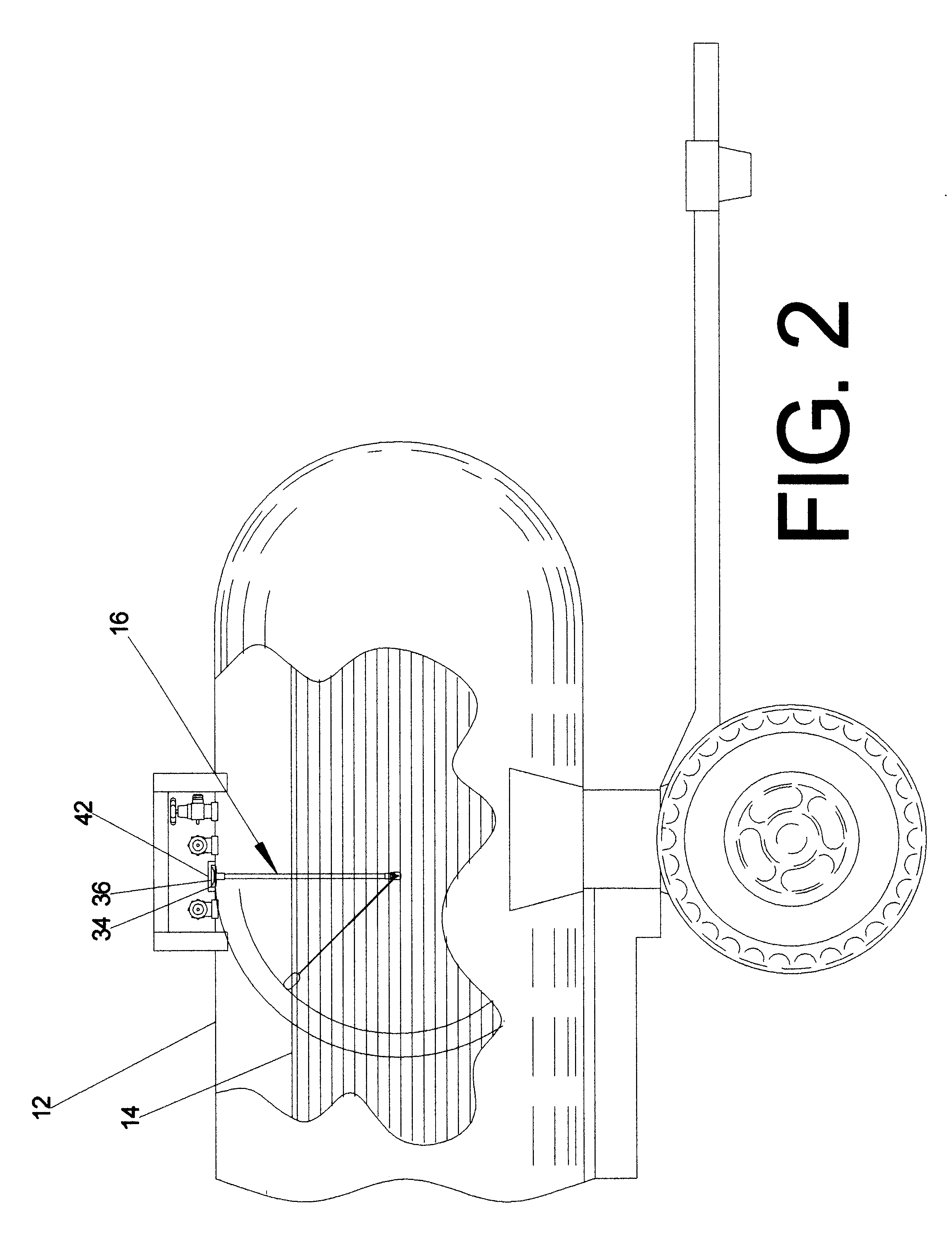
The tank module [40] is capable of measuring both pitch and roll measurements of the tank's [12] angle of incidence relative to the ground plane by means of a 2-axis electronic inclinometer [60]. Since most internal gauge mechanisms are mounted axially within the field tank [12], the pitch of the field tank [12] will have by far the largest effect on possible measurement errors associated with uneven terrain, as opposed to roll which would be encountered frequently in contour farming and does not have a significant effect on float position. The tank module [40] compensates for erroneous float positions due to pitch inclines or declines by combining the information from the electronic inclinometer [60] with the current averaged fluid level.
FIG. 23 details a fluid containing tank on an incline. As the tank goes up a hill, for instance, the inclinometer [60] will measure the angle of the field tank relative to the ground pl...
example 3
Determination of "Sleep Time" Between Fluid Level Readings
The microcontroller varies the amount of time it sleeps between fluid level samples depending on the amount of fluid remaining in the tank as a means to conserve battery power, while enhancing performance and accuracy of fluid level measurements.
It is known, based on the cylindrical geometry of the tank, that for any given flow rate of fluid from the field tank, that the rate of movement of the float arm will be greater at the upper and lower portions of the tank than it will be in the mid-section. This is because most of the volume of the tank is contained within the mid-section of the tank, so there is a smaller change in fluid level for any given quantity of fluid dispensed. The sampling rate, or duration of time that the microcontroller "sleeps" between samples, is selected from a look-up table within the tank module's onboard memory. Suitably, ten different sample periods are available to the microcontroller depending on...
PUM
 Abstract
Description
Claims
Application Information
 - R&D
- Intellectual Property
- Life Sciences
- Materials
- Tech Scout
- Unparalleled Data Quality
- Higher Quality Content
- 60% Fewer Hallucinations
Browse by: Latest US Patents, China's latest patents, Technical Efficacy Thesaurus, Application Domain, Technology Topic, Popular Technical Reports.
© 2025 PatSnap. All rights reserved.Legal|Privacy policy|Modern Slavery Act Transparency Statement|Sitemap|About US| Contact US: help@patsnap.com


