
Heat-sealing method and apparatus for fiber sheets

a heatsealing apparatus and fiber sheet technology, applied in lighting and heating apparatus, manufacturing tools, furniture, etc., can solve the problems of poor fusing efficiency of relatively bulky sheets and difficulty in high-speed treatmen

Inactive Publication Date: 2004-03-30
UNI CHARM CORP
View PDF11 Cites 10 Cited by
  • Summary
  • Abstract
  • Description
  • Claims
  • Application Information

AI Technical Summary

Benefits of technology

When the rolls are rotated and fed inbetween with a bulky fiber sheet, according to the invention, the fiber sheet is clamped by the insulator to expel the air from the fiber sheet to the outside, so that it is clamped by the sealing ridges when the air is expelled to a considerable extent. At the instant when the fiber sheet is clamped by the sealing ridges, therefore, the void volume in the fiber sheet is reduced so that the fusible fibers in the fiber sheet are quickly heated by the heat of the sealing ridges. Therefore, the reliable heat-sealing can be ensured even if the rotating speed of the rolls is increased to raise the feeding rate of the fiber sheet.

Problems solved by technology

The heat-sealing method using the rolls 31 and 32, as shown in FIG. 7, can perform the high-speed treatment when it is to fuse a less bulky nonwoven fabric or the like but is defective in that it has a poor fusing efficiency for a relatively bulky sheet such as the fiber sheet 10 including the fiber web 12 opened from TOW and is difficult to perform the high-speed treatment.

Method used


Image

  • Heat-sealing method and apparatus for fiber sheets
  • Heat-sealing method and apparatus for fiber sheets
  • Heat-sealing method and apparatus for fiber sheets

Examples


Embodiment Construction

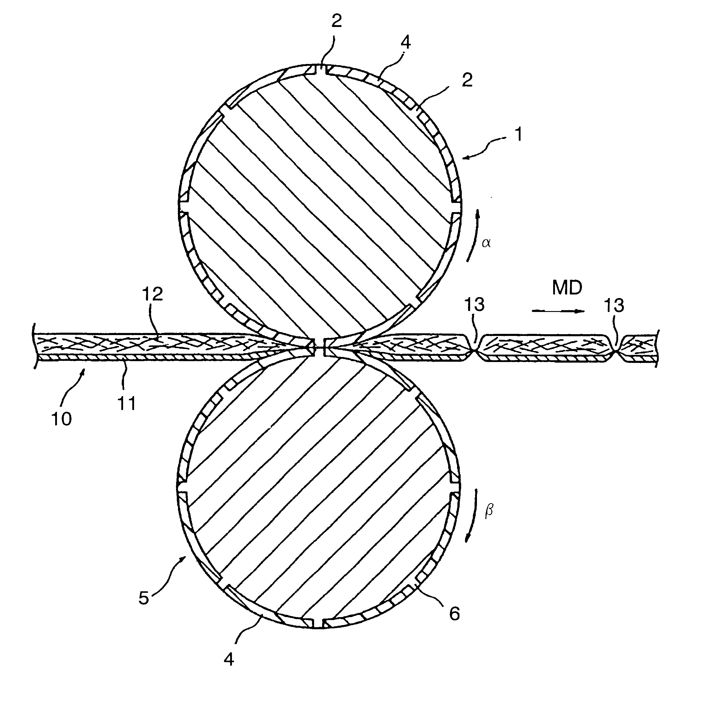
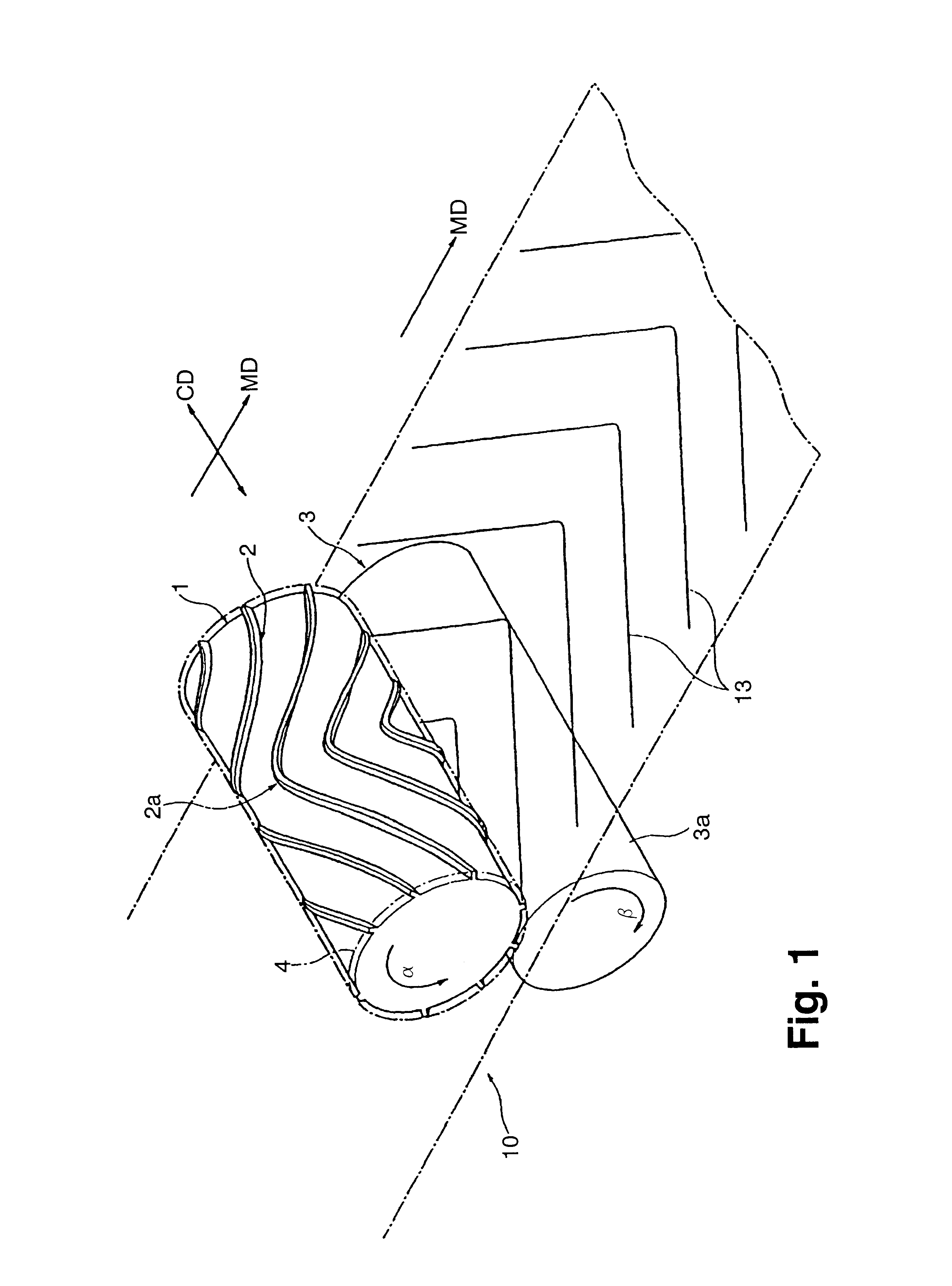
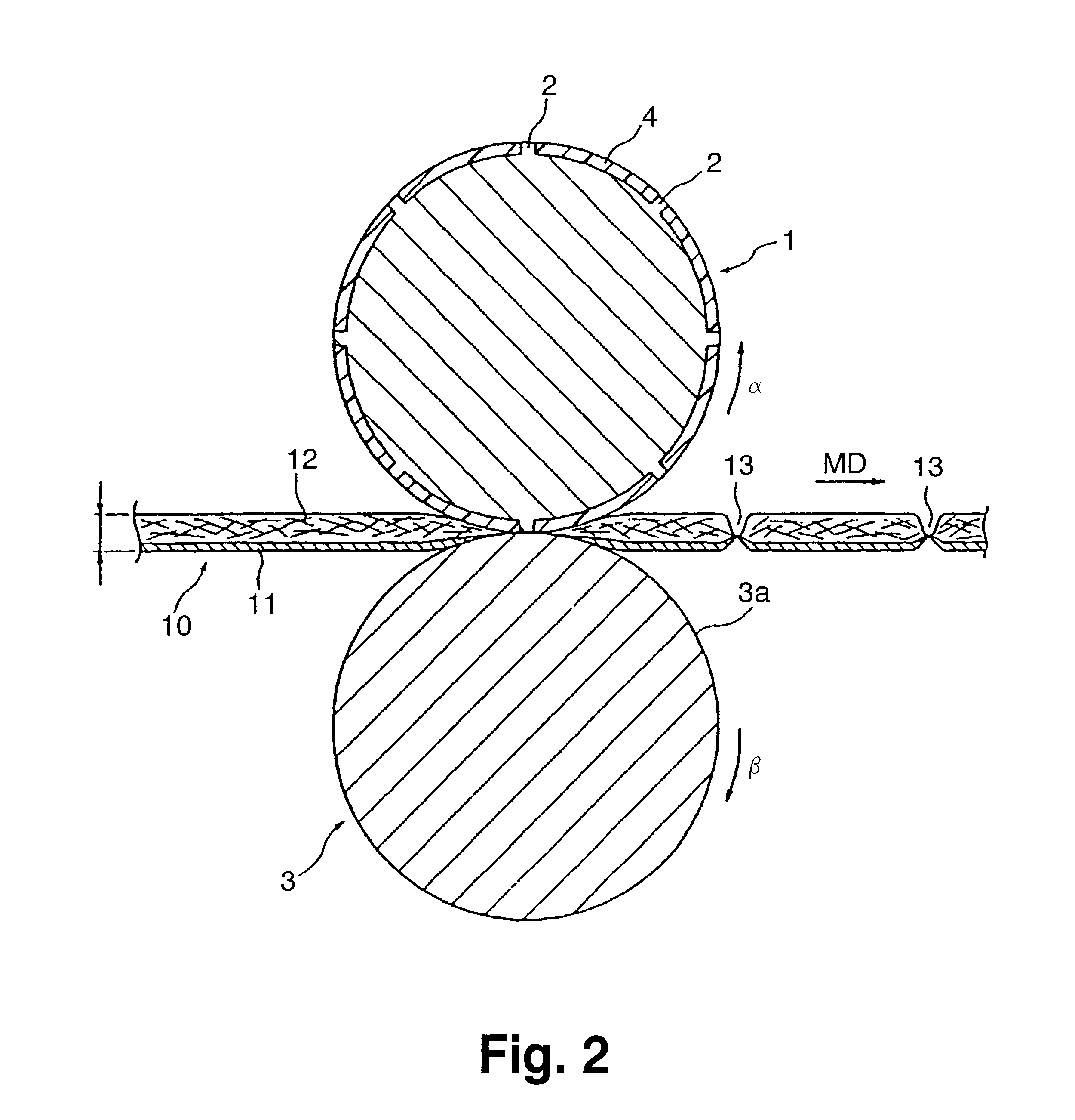
FIG. 1 is a perspective view of a heat-sealing apparatus for executing a heat-sealing method according to one embodiment of the invention; FIG. 2 is a sectional view showing a step of forming fused portions in a fiber sheet by the heat-sealing apparatus of FIG. 1; and FIG. 3 is a sectional view showing another embodiment of the heat-sealing method and the heat-sealing apparatus.

In FIG. 1, there are shown a pair of rolls 1 and 3. These two rolls 1 and 3 are made of a metallic material having a high thermal conductivity such as steel or an alloy. Of these, one is the pattern roll 1 which is integrally provided with sealing ridges 2 on its outer circumference. These sealing ridges 2 are formed circumferentially in a plurality of patterns at a predetermined interval and are patterned into a shape of letter "V", the crests 2a of which are directed forward (i.e., in the direction .alpha.) of the rotating direction of the pattern roll 1.

As shown in FIG. 2, the outer circumference of the pa...


PUM

PropertyMeasurementUnit
thermal conductivityaaaaaaaaaa
thicknessaaaaaaaaaa
pressureaaaaaaaaaa

Abstract

There is disclosed a heat-sealing method including: feeding a fusible fiber sheet (12) into the clearance between a pair of rolls (1, 5), at least one of which has sealing ridges (2, 6) of a predetermined pattern on its outer circumference; and heating and pressing the fiber sheet (12) with the sealing ridges (2, 6), to form fused portions corresponding to the pattern of the sealing ridges (2, 6), in the fiber sheet (12). An insulator (4) is disposed to cover the outer circumference of the rolls (1, 5), as lacking the sealing ridges. The insulator (4) is made of a material which has a lower thermal conductivity than that of the sealing ridges and which can be elastically contracted by the pressure of the rolls (1, 5). The fiber sheet (12) to be fed into the clearance between the rolls (1, 5) rotating is compressed by the insulator (4) to discharge its internal air and is then heated and pressed by the sealing ridges (2, 6) so that it is heat-sealed.

Description

1. Field of the InventionThe present invention relates to a heat-sealing method and a heat-sealing apparatus for fusing a fiber sheet of a bulky nonwoven fabric, a fiber web, a composite of a nonwoven fabric and a fiber web, a composite of a film and a fiber web, a composite of a film, a nonwoven fabric and a fiber web, or the like into a predetermined pattern.2. Description of the Prior ArtA fiber sheet of a nonwoven fabric, a fiber web or the like may be partially fused and used as a cleaning sheet. In Unexamined Published Japanese Patent Application No. 11-235301, for example, there is disclosed a cleaning sheet which is manufactured by heat-sealing a fiber sheet, as prepared by overlapping a fiber web of long fibers opened from TOW on a nonwoven fabric, partially and by slitting the nonwoven fabric and the fiber web in the region between fused lines formed by heat-sealing. In this cleaning sheet, the fiber web can sweep dust easily with brush-shaped portions, each of which is lo...

Claims


Application Information

Patent Timeline
Patent Type & Authority Patents(United States)
IPC IPC(8): B29C65/00B29C65/02D04H13/00D04H1/54B32B5/26D04H3/14
CPCB29C65/02B29C66/005B29C66/83411B29C66/83511B32B37/065D04H13/007B29C66/83513Y10T156/1741B29K2105/0854B29L2009/00B29C66/7294B29C66/8122B29C66/81241B29C66/71B29C66/43B29C65/18B29C66/45B29C66/472B29C66/81261B29C66/81821B29C66/723B29C66/1122B29K2883/00B29K2067/003B29K2023/06B29K2023/12D04H1/54D04H3/14
Inventor TANAKA, YOSHINORIKENMOCHI, YASUHIKO
Owner UNI CHARM CORP
Learn More