Method and system for determining induction motor speed

a technology of induction motor and speed, which is applied in the direction of motor/generator/converter stopper, dynamo-electric gear control, motor/generator/converter stopper, etc., can solve the problem of unsuitable introduction of transducers or other physical sensors for measuring, the cost of speed sensor installation could be comparable to the cost of the motor itself, and the probability of failure of the speed sensor is higher than the probability of failur

Inactive Publication Date: 2004-03-30
TEXAS A&M UNIVERSITY
View PDF14 Cites 38 Cited by
  • Summary
  • Abstract
  • Description
  • Claims
  • Application Information

AI Technical Summary

Problems solved by technology

However, it is generally undesirable to introduce transducers or other physical sensors for measuring the speed or the position of a rotating rotor because of the additional cabling and increased costs.
For example, for a small motor, such as 5 horsepower or less, the cost of speed sensor installation could be comparable to the cost of the motor itself.
Also, the probability of failure of the speed sensor is higher than the probability of failure of the small motor.
The model based speed estimation methods are inconvenient because they have to rely on detailed motor parameters, i.e., a priori knowledge of the motor's electrical (and in some cases mechanical) characteristics, in order to operate properly.
However, those parameters are typically available only to the designer of the motor.
Further, many motor based speed estimation methods assume linear motor models and time invariant parameters, which leads to poor speed estimation.
The RSH based speed estimation methods are not completely acceptable either because they sometimes perform poorly at low motor speeds due to difficulty in tracking low frequency harmonics.
Additionally, RSH based speed estimation methods require the calculation of the Fast Fourier Transform (FFT) of the stator current, and as a result, RSH based speed estimation methods inherit all the typical limitations of an FFT based scheme.
Also, for certain rotor-stator slot combinations, primarily those at lighter loads, the RSH may not be readily detectable.
While the transient speed can be calculated by using a moving window, it leads to poor time localization of the estimated speed response.
Moreover, FFT based schemes are computationally burdensome for real-time implementation, and more expensive data processing equipment is needed, which would offset any cost advantages the RSH based speed estimation methods might deliver.

Method used


Image

  • Method and system for determining induction motor speed
  • Method and system for determining induction motor speed
  • Method and system for determining induction motor speed

Examples


Embodiment Construction

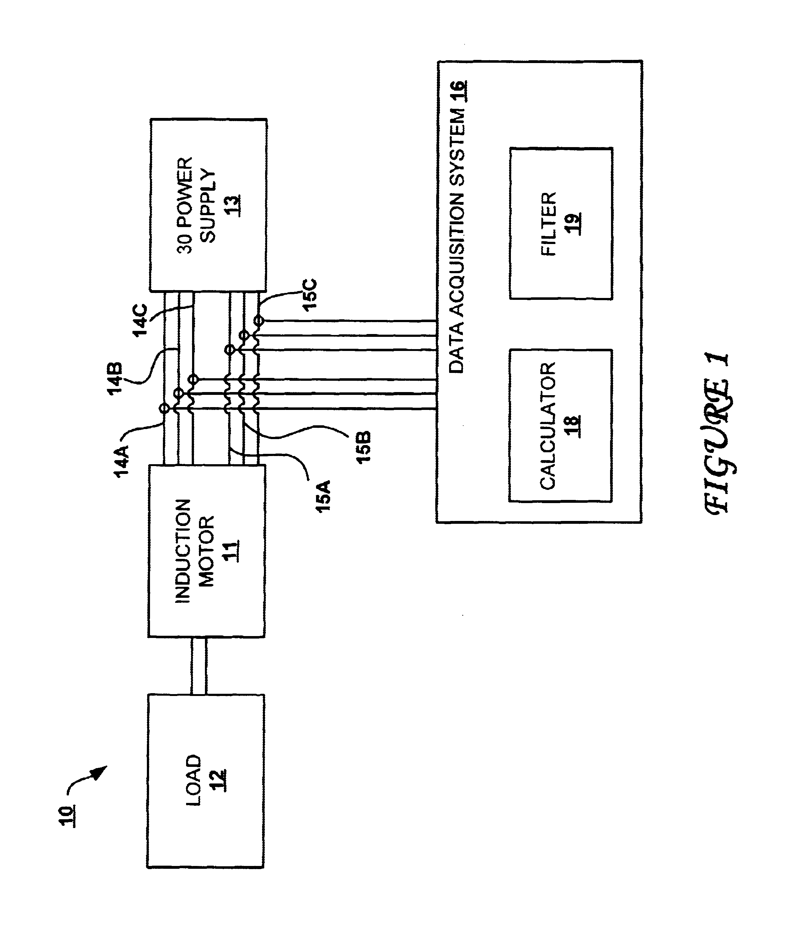
Referring now to the drawings and in particular to FIG. 1, there is depicted a block diagram of an induction motor assembly, in accordance with a preferred embodiment of the present invention. As shown, an induction motor assembly 10 includes an induction motor 11, a three-phase power supply 13, and a data acquisition system 16. Induction motor 11 is preferably a three-phase motor that is powered by three-phase power supply 13 via three voltage inputs 14a-14c and three current inputs 15a-15c. It is understood by those skilled in the art that induction motor 11 can be of any size having any number of phases. Induction motor 11 is shown to be connected to a load 12. Data acquisition system 16 is operably associated with each of voltage inputs 14a-14c and each of current inputs 15a-15c via a respective hall-effect detector (not shown) that is well-known to those skilled in the art. The hall-effect detectors can unintrusively detect or measure the voltage values at voltage inputs 14a-14...


PUM


Abstract

A non-linear, semi-parametric neural network-based adaptive filter is utilized to determine the dynamic speed of a rotating rotor within an induction motor, without the explicit use of a speed sensor, such as a tachometer, is disclosed. The neural network-based filter is developed using actual motor current measurements, voltage measurements, and nameplate information. The neural network-based adaptive filter is trained using an estimated speed calculator derived from the actual current and voltage measurements. The neural network-based adaptive filter uses voltage and current measurements to determine the instantaneous speed of a rotating rotor. The neural network-based adaptive filter also includes an on-line adaptation scheme that permits the filter to be readily adapted for new operating conditions during operations.

Description

1. Technical FieldThe present invention relates to a method and system for determining the speed of induction motors in general, and in particular to a neural network-based method and system for determining the dynamic speed of induction motors.2. Description of the Related ArtInduction motors are commonly found in power plants and various types of manufacturing facilities throughout the world. An induction motor typically includes a stationary stator and a rotatable rotor. The ability to accurately determine the speed of a rotating rotor with respect to a stationary stator within an induction motor is vitally important to the every day operations of induction motors. However, it is generally undesirable to introduce transducers or other physical sensors for measuring the speed or the position of a rotating rotor because of the additional cabling and increased costs. For example, for a small motor, such as 5 horsepower or less, the cost of speed sensor installation could be comparab...

Claims


Application Information

Patent Timeline
Patent Type & Authority Patents(United States)
IPC IPC(8): H02P21/14G06N3/04
CPCG06N3/0454H02P21/0014H02P21/146H02P21/18H02P23/0018G06N3/045
Inventor PARLOS, ALEXANDER G.BHARADWAJ, RAJ M.
Owner TEXAS A&M UNIVERSITY
Why Eureka
Try Eureka