Waterproof counterweighted pit lid

a technology of counterweights and lids, which is applied in the direction of hinges, wing accessories, manufacturing tools, etc., can solve the problems of lid mounting systems, difficult to open such access lids without assistance, and heavy weight of pit access lids in aircraft servicing pits

Inactive Publication Date: 2004-04-06
CAVOTEC ACQUISITION US
View PDF5 Cites 13 Cited by
  • Summary
  • Abstract
  • Description
  • Claims
  • Application Information

AI Technical Summary

Problems solved by technology

The pit access lids in such aircraft servicing pits are extremely heavy, since they must be able to withstand the weight of the wheels of a large aircraft traveling thereacross.
Therefore, it is often very difficult to open such access lids without assistance.
Spring assisted pit lid mounting systems have certain disadvantages, however.
With age and exposure to the elements the springs can rust and break.
However, one disadvantage of existing gravity assisted pit mounting systems is that it has not heretofore been possible to provide a liquid-tight seal for lids mounted in this manner about their entire periphery.
As a consequence, there can be leakage into the pits from rain and melting snow that seeps into the mouth of the pit at the hinge opening.
This is because the mounting systems for conventional gravity assisted pit lids have not heretofore provided a complete seal at the top of the pit.
This latter feature is a disadvantage of conventional counterweighted pit lid systems.
The impact can damage the structure of the pit, if the pit lid is thrown or blown open.
This can occur either due to inattention on the part of the servicing personnel, or due to the force of wind or exhaust blasts from jet airplanes in the vicinity.
In either case, the structural integrity of the pit is compromised if the counterweights severely impact the wall of the pit.
The shock absorbers dampen the impact of the counterweights against the pit wall, and may indeed prevent any contact at all.

Method used


Image

  • Waterproof counterweighted pit lid
  • Waterproof counterweighted pit lid
  • Waterproof counterweighted pit lid

Examples


Embodiment Construction

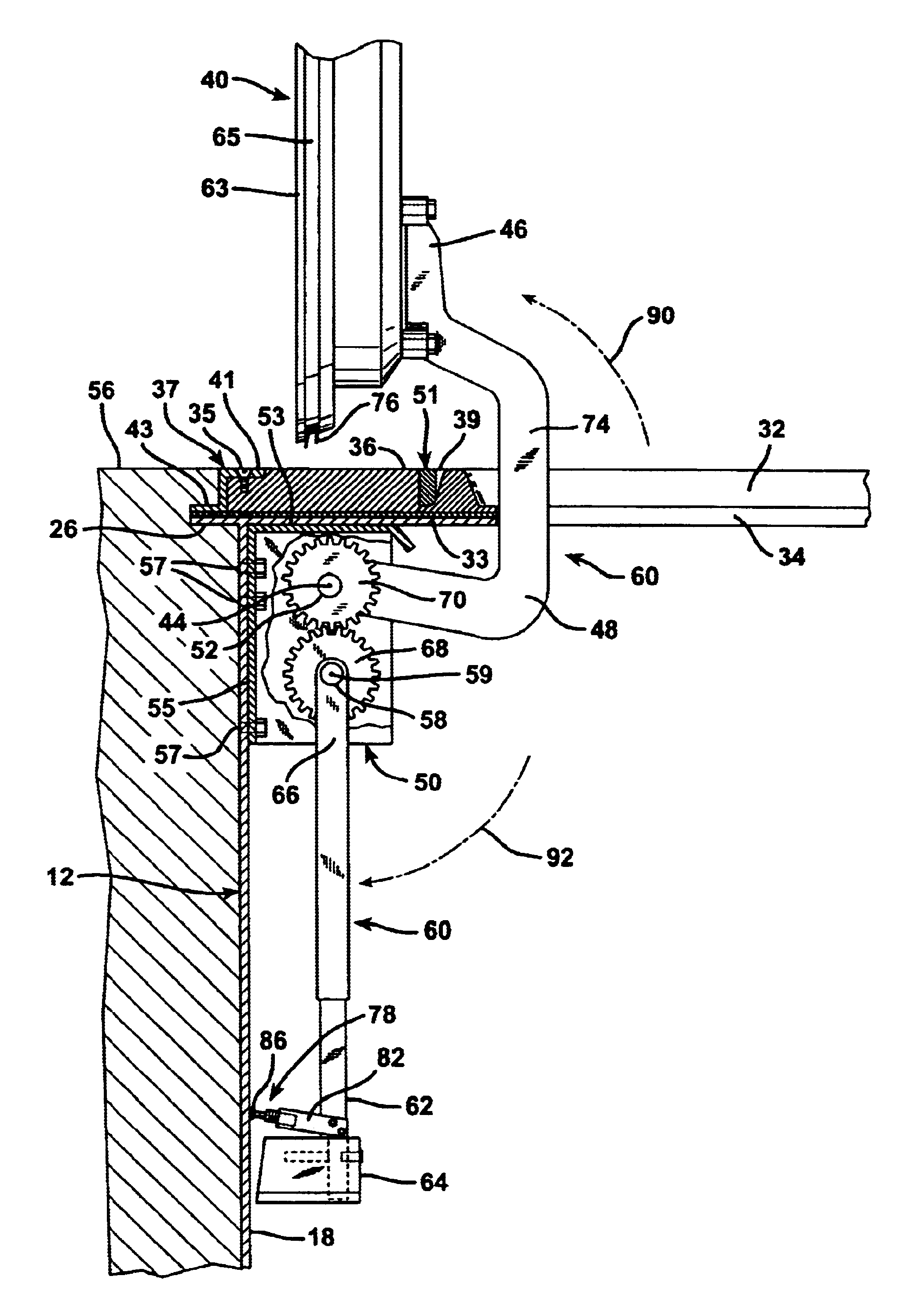
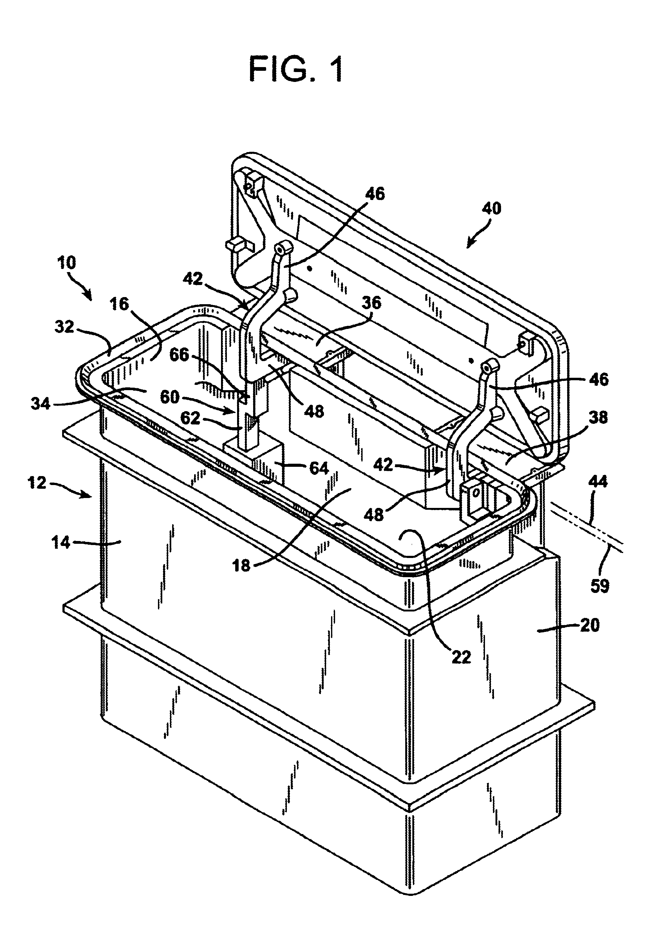
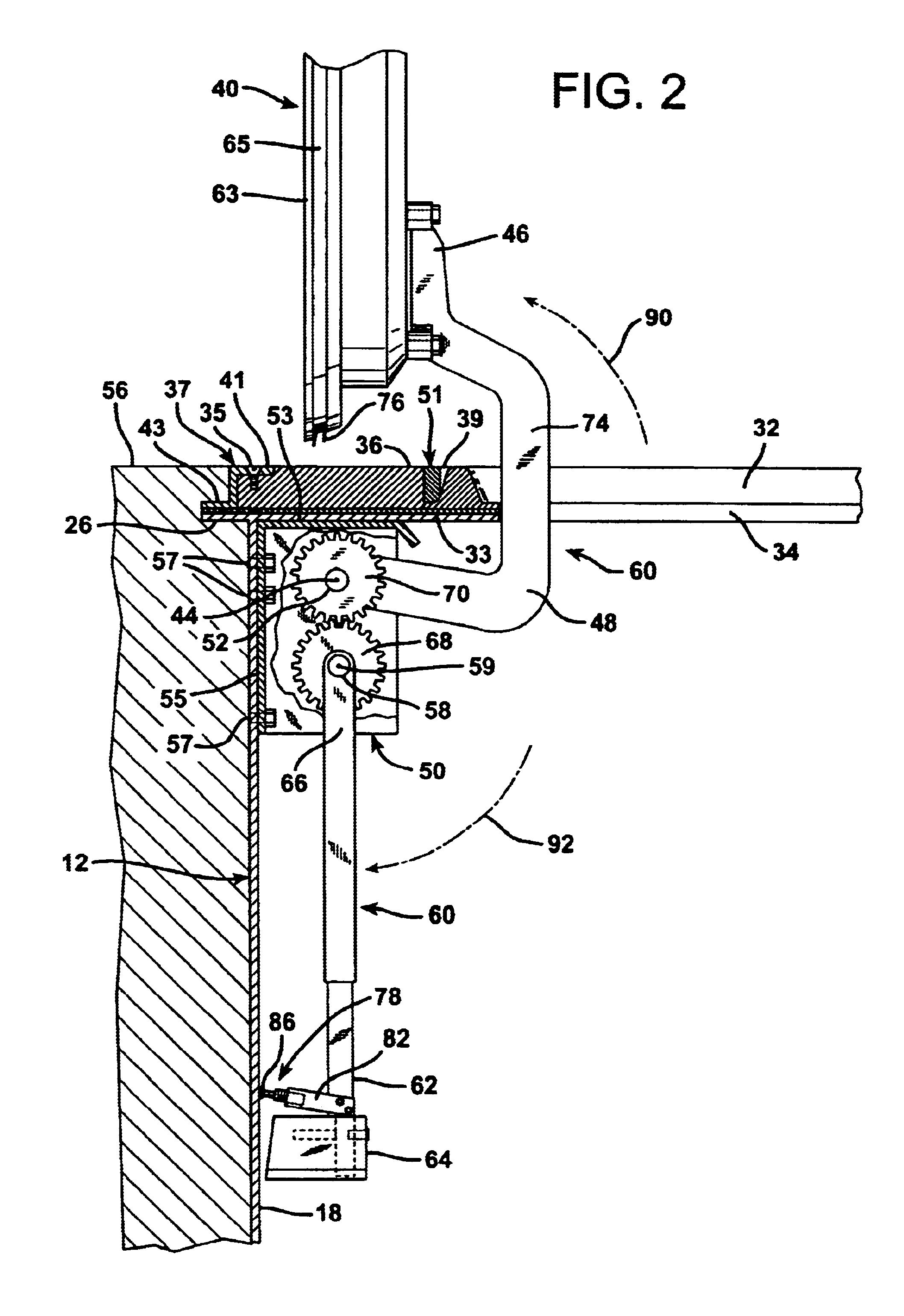
FIG. 1 illustrates an aircraft servicing pit 10 of the type installed below a surface across which aircraft travel when not airborne. The aircraft servicing pit 10 is formed with a prefabricated, molded fiberglass resin reinforced shell or body 12 having at least one, and more typically a plurality of upright generally vertically oriented walls. The fiberglass reinforced pit body 12 is shown in isolation in FIG. 5. The molded pit body 12 has a generally rectilinear shape so that the upright walls 14, 16, 18, and 20 are oriented generally at right angles and surround and delineate a generally rectangularly shaped subsurface enclosure indicated generally at 22. At its upper extremity the pit body 12 has a neck end 24 that terminates in an outwardly directed horizontal flange 26. At its rear upright wall 18 the fiberglass pit body 12 is formed with a pair of hinge pocket openings 28 and 30.

The subsurface fiberglass pit 10 is also provided with a continuous metal rim 32 that is formed w...


PUM


Abstract

An aircraft servicing pit that defines a subsurface chamber below a surface across which aircraft travel when not airborne is formed of a prefabricated pit body atop which a pit lid is mounted for rotation. Within the enclosure of the pit beneath the surface across which the aircraft travel a counterweight system is connected by gears to pit lid supporting arms. The pit lid supporting arms have proximal ends rigidly joined to pit lid gears, which are meshed with counterweight gears rigidly joined to counterweight arms supporting counterweights within the enclosure of the pit. The pit lid and counterweight arms move in counterrotation when the pit lid is opened and closed, with the gravitational force acting upon the counterweights acting in opposition to the force of gravity upon the pit lid. By locating the lid hinge axis of rotation beneath the rim of the frame in which the pit lid is seated when closed, it is possible to provide the pit lid with a resilient gasket extending about its entire peripheral edge. Consequently, an aircraft servicing pit is provided which has a counterbalanced pit lid that may be sealed watertight within a surrounding frame.

Description

1. Field of the InventionThe present invention relates to a self-sealing gravity assisted pit lid mounting system for an access lid to a subsurface chamber for servicing aircraft.2. Description of the Prior ArtAt modern aircraft terminals the servicing of aircraft on the ground is frequently performed using subsurface pits, which are often prefabricated structures. Such aircraft servicing pits are installed at aircraft docking, fueling, and loading areas beneath the surface of the tarmac across which aircraft travel during docking and departure maneuvers. The pits forming a subsurface chamber are typically constructed of fiberglass, steel, concrete, or aluminum. These pits are typically fabricated as complete enclosures with surrounding walls, a floor, and an access lid at the top seated within a frame disposed at the mouth of the prefabricated pit. When the lid is closed it lies substantially flush with the surface of the tarmac. Such pits are installed below the surface of loading...

Claims


Application Information

Patent Timeline
Patent Type & Authority Patents(United States)
IPC IPC(8): B64F1/00
CPCB64F1/00Y10T16/53834
Inventor PETERSEN, CRAIG
Owner CAVOTEC ACQUISITION US
Why Eureka
Try Eureka