
Multiple pressure regulator

a pressure regulator and multi-function technology, applied in the direction of valve housings, volume meters, instruments, etc., can solve the problems of multiple downtime of any single regulator, only feasible use of multiple fuel regulators, etc., to improve flow linearity, reduce turbulence, and precise spacing

Inactive Publication Date: 2004-04-20
MAGNUM TOOL CO INC +1
View PDF19 Cites 15 Cited by
  • Summary
  • Abstract
  • Description
  • Claims
  • Application Information

AI Technical Summary

Benefits of technology

"The invention is a pressure regulator design that solves common problems by using a cartridge carrying a valve, a valve seat, and a biasing means. This design eliminates the need for intricate stacking of small parts, calibration, and multiple fuel inlet hoses. It also reduces turbulence in flow, improves flow linearity at varying flow rates and pressures, and facilitates tuning and adjustment in the field. The invention also includes a multiple pressure regulator design that simplifies field installation and reduces installation time. Additionally, a fuel enrichment balancing system is provided that is problem-free, reliable, and user-friendly. The invention also includes a valve cartridge that can be easily removed and replaced to alter pressure flow characteristics."

Problems solved by technology

The possibility of using a multiple fuel regulator is only feasible with the use of valve cartridges in the regulators therein.
Without readily replaceable valve cartridges, which dramatically reduce pressure regulator problems and facilitate quick rectification of any problem, the use of a multiple regulator would otherwise result in a multiple of the down time of any one individual regulator; and this would be unacceptable.

Method used


Image

  • Multiple pressure regulator
  • Multiple pressure regulator

Examples


Embodiment Construction

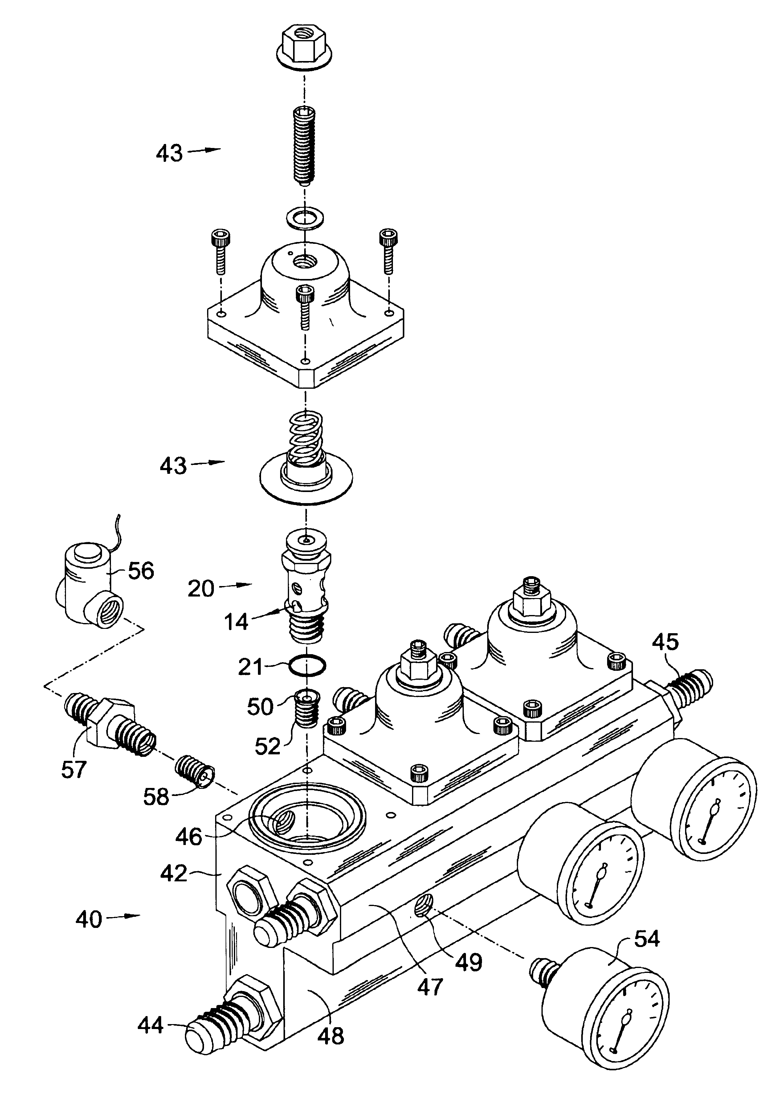
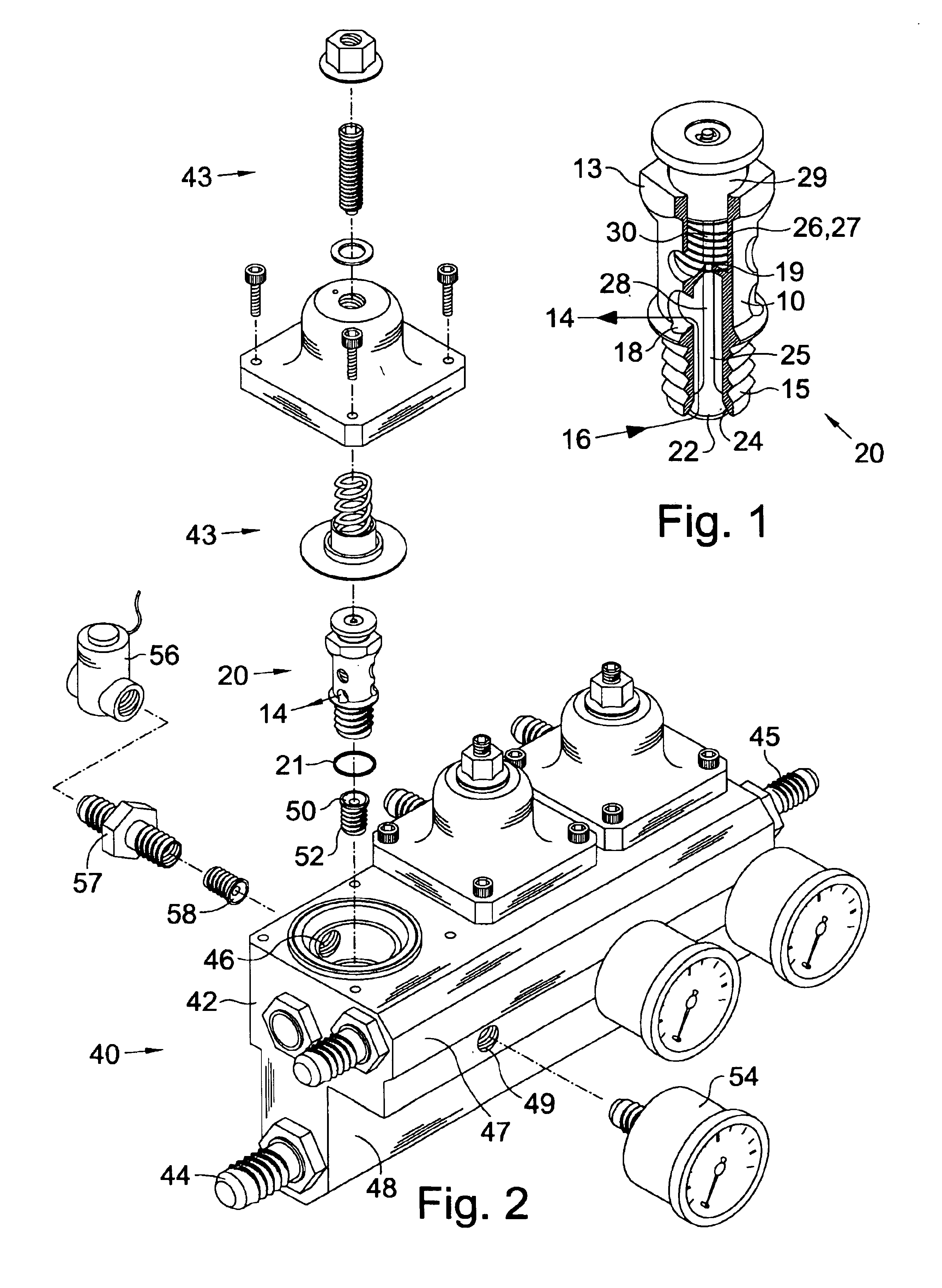
Turning now to the drawings and more particularly to FIG. 1 we have an enlarged perspective view of a replaceable valve cartridge 20 comprising a valve cartridge frame 10 which carries and positions a valve member 22, a valve stem 28, a valve seat 24, and a valve bias means 26. The valve cartridge 20 is removably held in a pressure regulator 40 of the type having a housing 42; an inlet 44 into the housing 42; an outlet 46 from the housing 42; and a valve stem positioning and adjusting means 43 to adjust the pressure. The valve cartridge 20 also maintains the critical spacing between the valve member 22 and the valve seat 24. Difficulties in pressure regulation may be quickly rectified and pressure flow characteristics may be altered by removing and replacing the valve cartridge 20. Using a pressure regulator 40 having a replaceable valve cartridge 20 has a particular advantage in vehicle racing fuel delivery systems where adjustments must be made in the field on a fuel pressure regu...


PUM


Abstract

A pressure regulator having a valve cartridge adapted to be removably held within its housing, said cartridge having a frame carrying and positioning a valve seat, a valve member, a valve stem, and a spring. The valve cartridge ensures correct spacing between the valve member and the valve seat. Difficulties in pressure regulation may be quickly rectified and pressure flow characteristics may be altered by removing and replacing the valve cartridge. Another aspect of the invention discloses a multiple pressure regulator comprising: a housing adapted to removably house two valve cartridges; an inlet opening into the housing; an outlet opening from the housing; and two valve cartridges adapted to be removably held within the housing. Each of said cartridges similar to those described above. In a preferred aspect of the invention the multiple pressure regulator comprises an inlet manifold to stabilize pressure fluctuations, and said housing is internally plumbed so that a common feed return line can recirculate flow received through the inlet opening, and so that a pressure meter connected thereto may monitor flow pressure on each valve cartridge.

Description

This invention relates to pressure regulators. More particularly this invention relates to a multiple pressure regulator having a removable cartridge containing a valve and seat having particular application for enriching fuel mixtures in racing.The applicant designs and markets racing fuel systems. Regulators used to enrich fuel mixtures in racing generally comprise a stack up of components within a regulator housing. They are dependent on proper and intricate assembly for proper function. Frequently they must be returned to the manufacture for service. In the field users frequently need to adjust and tune the flow and pressure characteristics of the unit. No adjustment can be readily made without unstacking and subsequently restacking intricate and easily lost small parts. Another problem with a stack up design is the necessity of precise spacing between the metering valve member and the valve seat; this distance must be recalibrated each time the stack is replaced after inspectio...

Claims


Application Information

Patent Timeline
Patent Type & Authority Patents(United States)
IPC IPC(8): F16K27/00F16K15/06F16K15/02
CPCF16K15/066F16K27/003Y10T137/5987Y10T137/599Y10T137/7613Y10T137/7795Y10T137/7796Y10T137/7801Y10T137/8326Y10T137/87877
Inventor MCADEN, ROBERT A.
Owner MAGNUM TOOL CO INC
Learn More