Diffractive optical element that polarizes light and an optical pickup using the same
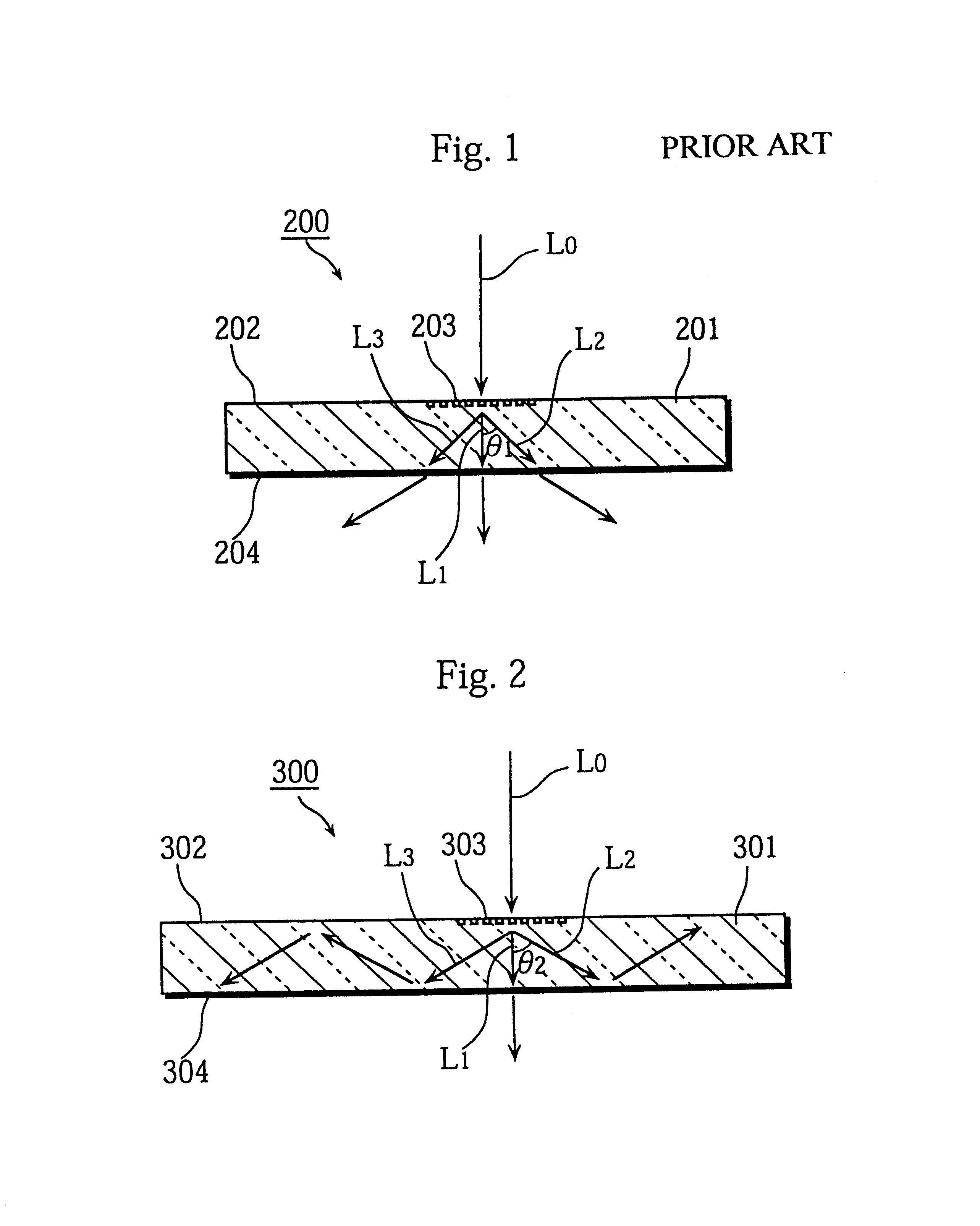
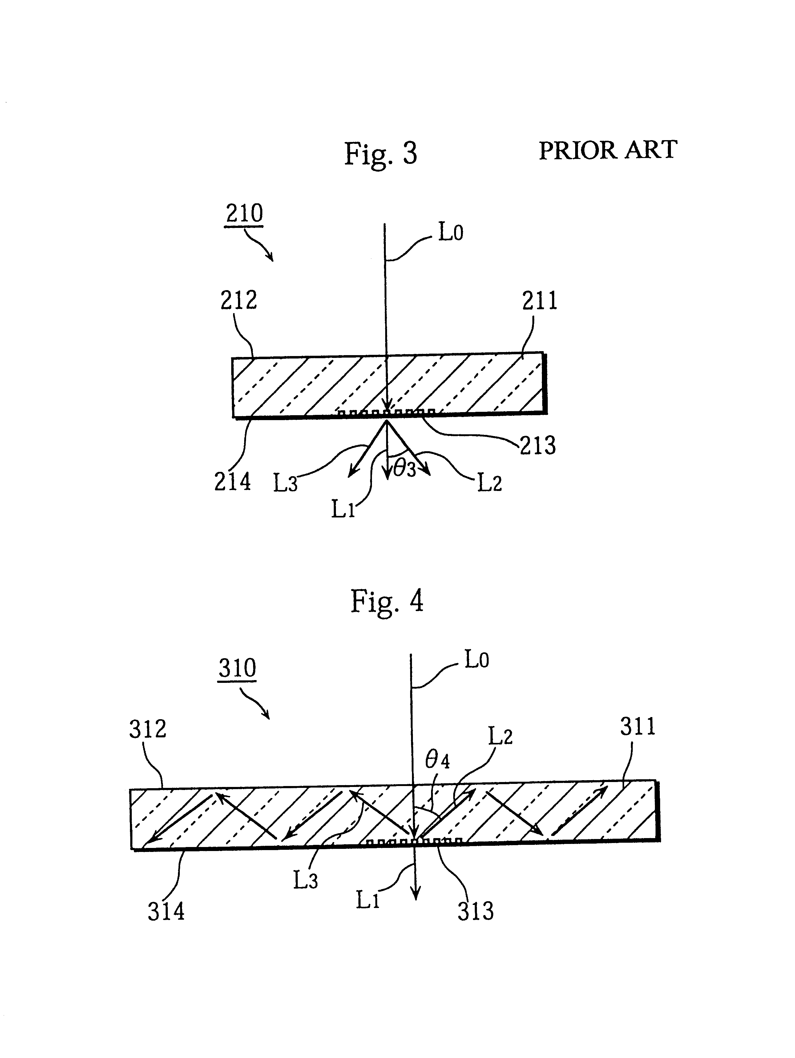
a technology of diffracted light and optical elements, applied in the direction of polarising elements, instruments, light beam reproducing, etc., can solve the problems of diffracted light trapped in the substrate, limiting the potential of optical elements on such substrates, and diffraction of light trapped within the substra
- Summary
- Abstract
- Description
- Claims
- Application Information
AI Technical Summary
Problems solved by technology
Method used
Image
Examples
first embodiment
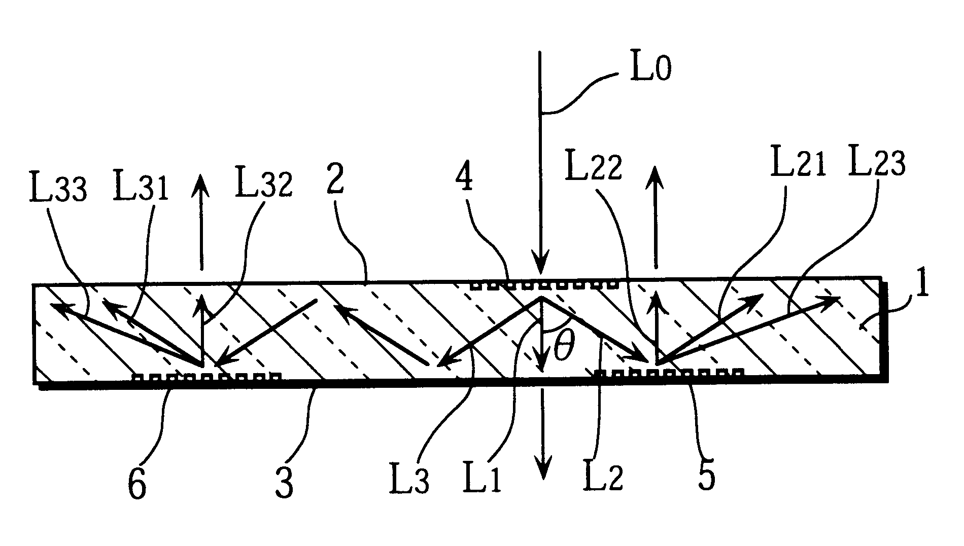
FIG. 5 is a perspective drawing showing the external appearance of a transmittive-polarization type diffractive optical element 100 to which the first embodiment of the present invention relates.
As shown in FIG. 5, the diffractive optical element 100 is composed of a substrate 1 that is made of a transparent substance such as glass and has a first diffractive optical element pattern 4 on a main surface 2 and second diffractive optical element patterns 5 and 6 formed on an opposite main surface 3.
The first diffractive optical element pattern 4 and second diffractive optical element patterns 5 and 6 are each composed of slits. The slits in the first diffractive optical element pattern 4 are formed with a rectangular cross-section and a pattern pitch that is no greater than the wavelength .lambda. of the incident light. This kind of pattern can be formed by dry etching, such as by performing reactive ion-beam etching (RIBE) in the presence of chlorine gas. As a diffractive optical elem...
second embodiment
FIG. 8 shows the construction of the diffractive optical element 110 of the second embodiment of the present invention. Unlike the diffractive optical element 100 of the first embodiment, this diffractive optical element 110 has the first diffractive optical element pattern 4 and the second diffractive optical element patterns 5 and 6 formed on the same main surface (main surface 2) of the substrate 1. Many construction elements are the same as those in the first embodiment, so that these have been given the same reference numerals as before and their explanation has been omitted.
As shown in FIG. 8, the diffractive optical element 110 is composed of a substrate 1 that has a polarizing first diffractive optical element pattern 4 on a main surface 2 and light-projecting second diffractive optical element patterns 5 and 6 positioned on the same main surface 2 so as to be incident to diffracted light that is produced by the first diffractive optical element pattern 4 and has been subjec...
third embodiment
FIG. 10 shows the construction of a diffractive optical element 120 of the third embodiment of the present invention.
As shown in FIG. 10, the diffractive optical element 120 is composed of a substrate 1 that has a polarizing first diffractive optical element pattern 4 on a main surface 2 and light-projecting second diffractive optical element patterns 9 and 10 on an opposite main surface 3. These second diffractive optical element patterns 9 and 10 are positioned so as to be either directly incident to diffracted light that is produced by the first diffractive optical element pattern 4 or incident to the diffracted light after it has been subjected to total internal reflection by the main surfaces two times. These second diffractive optical element patterns 9 and 10 are made up of slits that are triangular in cross-section and so will hereafter be referred to as "sawtooth patterns".
FIG. 11 is an enlargement of one of the slits that composes the second diffractive optical element pat...
PUM
| Property | Measurement | Unit |
|---|---|---|
| diffraction angle | aaaaa | aaaaa |
| refractive index | aaaaa | aaaaa |
| first-order diffraction angle | aaaaa | aaaaa |
Abstract
Description
Claims
Application Information
 - R&D
- Intellectual Property
- Life Sciences
- Materials
- Tech Scout
- Unparalleled Data Quality
- Higher Quality Content
- 60% Fewer Hallucinations
Browse by: Latest US Patents, China's latest patents, Technical Efficacy Thesaurus, Application Domain, Technology Topic, Popular Technical Reports.
© 2025 PatSnap. All rights reserved.Legal|Privacy policy|Modern Slavery Act Transparency Statement|Sitemap|About US| Contact US: help@patsnap.com


