Magnetic resonance imaging method and device

a magnetic resonance imaging and magnetic resonance technology, applied in the field of magnetic resonance imaging methods and devices, can solve the problems of actual improvement of image quality, image quality may suffer, improvement can exceed improvement, etc., and achieve the effect of improving the image quality of mr images

Inactive Publication Date: 2004-04-27
HITACHI MEDICAL CORP
View PDF6 Cites 18 Cited by
  • Summary
  • Abstract
  • Description
  • Claims
  • Application Information

AI Technical Summary

Benefits of technology

is to improve image quality of MR images acquired by an EPI method.

Problems solved by technology

In image data derived by the EPI method, a phase errors can be introduced that causes artifacts.
The main sources of such phase error in image data from the EPI method include non-uniformities in the MRI static magnetic field and eddy currents caused by the inversion of gradient magnetic field.
If the two methods are combined, it could be thought that the beneficial effect would increase, but corrections performed on data acquired by the ETS method through using reference data may not actually improve image quality, rather it can make an artifact be seen more clearly.
Even if correction is performed by a single set of reference data, the correction may not be performed precisely; accordingly image quality may suffer.
Such improvement can exceed the improvement resulting from using either method independently.

Method used


Image

  • Magnetic resonance imaging method and device
  • Magnetic resonance imaging method and device
  • Magnetic resonance imaging method and device

Examples


Embodiment Construction

FIG. 3 is a diagram that shows one example of an MRI apparatus embodying an example of the present invention. In FIG. 3, 302 is a magnet that generates a static magnetic field within a space for an object 301, e.g., a patient. 303 refers to gradient magnetic field coils that generate gradient magnetic fields in the space for object 301. 304 is an RF coil that irradiates a radio frequency magnetic field in said space. 305 is an RF probe that detects NMR signals generated by said object 301. Gradient magnetic field coils 303 comprise a respective gradient magnetic field coil for each of 3 directions --X, Y, Z. These directions are for a slice selection gradient magnetic field coil, a phase encoding gradient magnetic field coil, and a readout direction gradient magnetic field coil. Each coil generates gradient magnetic fields corresponding to signals supplied to each coil from a gradient magnetic field power source 309 for driving each coil. RF coil 304 generates radio frequency magnet...


PUM


Abstract

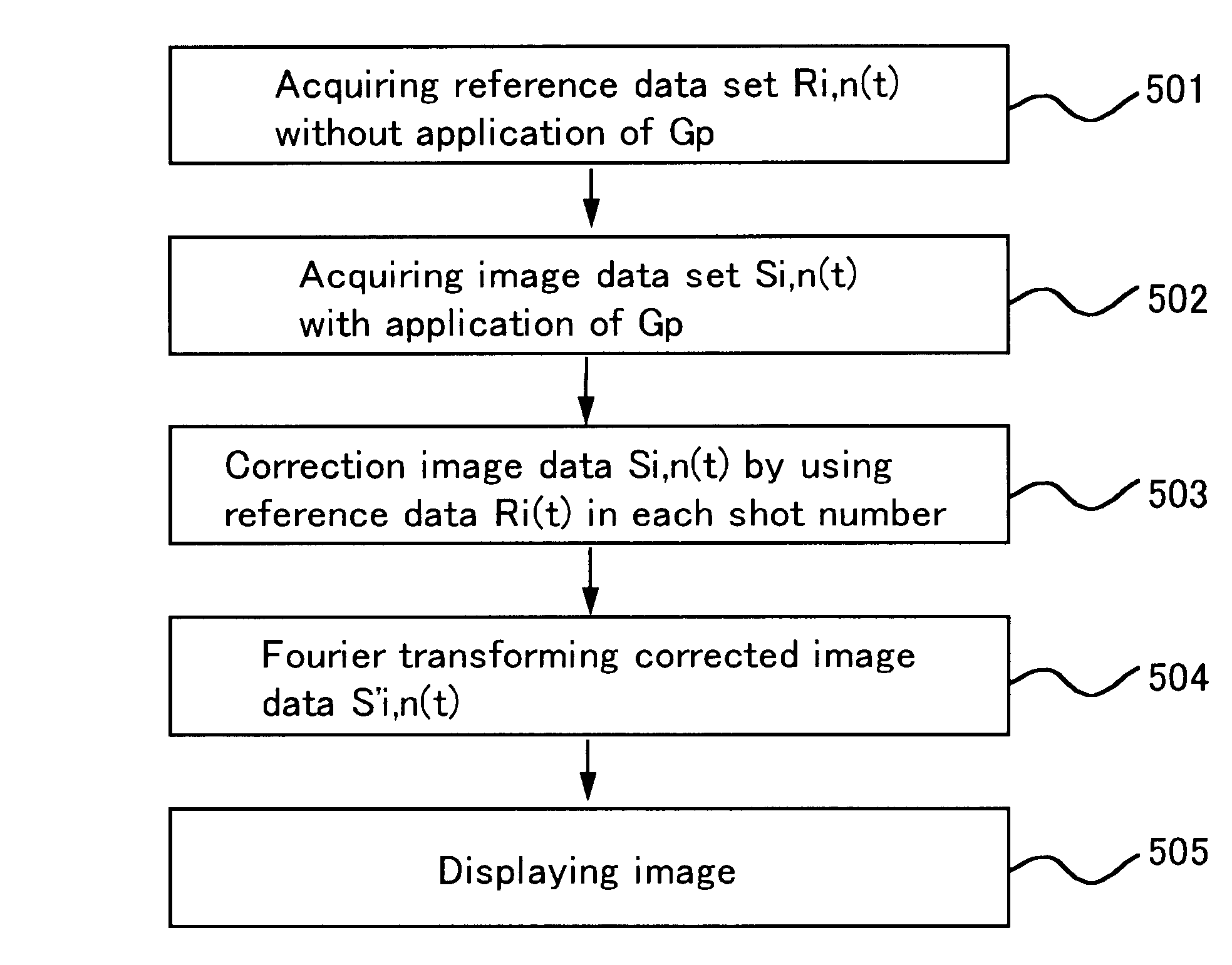
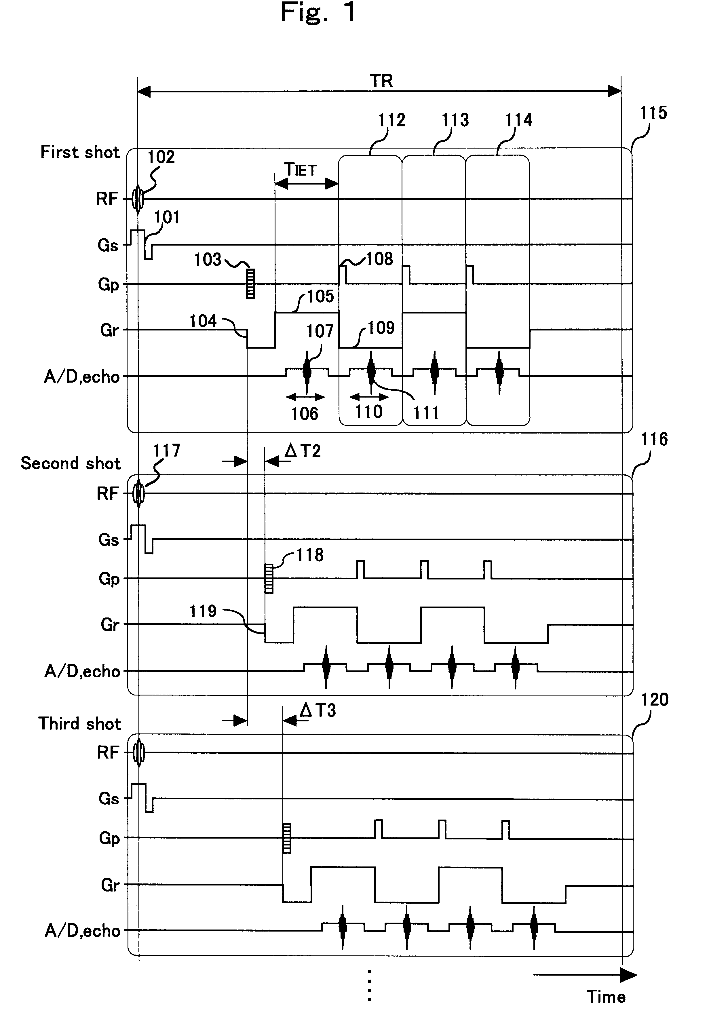
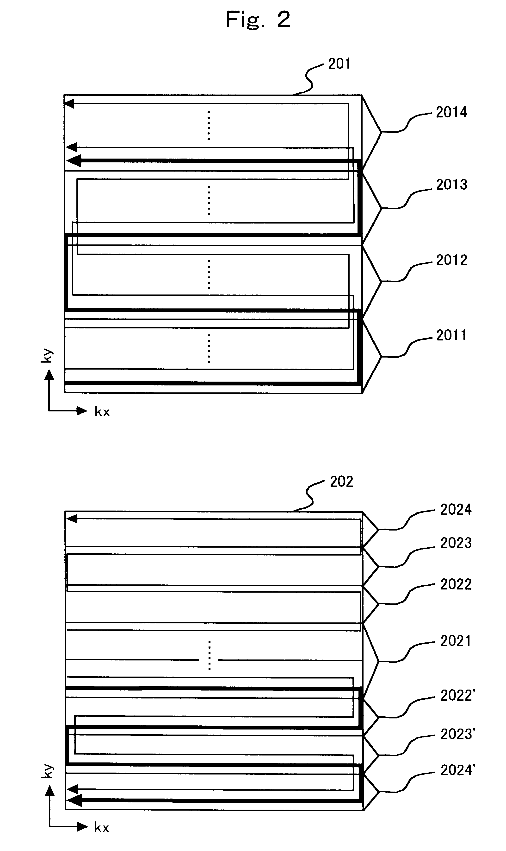
In order to improve image quality in MRI using an EPI method without extending imaging time excessively, reference data is acquired in the absence of substantial phase encoding gradients by using an EPI sequence in combination with an echo shift (ETS) method, at times related to the timing of echo signals for image data. The reference data is used for phase correcting the image data acquired with application of phase encoding. The reference data can be measured for a single shot, or a few shots, and used to estimate reference data for the rest of the shots in which imaging data is acquired.

Description

The present invention relates to magnetic resonance imaging (MRI) method and apparatus, particularly to techniques for removing artifacts in ultra fast MR imaging methods.BACKGROUND OF THE ARTMRI devices measure spatial distributions of proton density within an object to be examined and spatial distributions of relaxation times from excited states, and form images from measured data. In this manner, MRI devices reveal anatomical and physiological information regarding the human body, head, retroperitoneum, or the like, and create two-dimensional or three-dimensional images for display.MRI imaging involves applying phase encoded gradient magnetic fields to nuclear spins excited by radio frequency magnetic fields to generate echo signals. The phase encode levels usually are 128, 256, 512 or the like per image. Each echo signal usually is sampled at 128, 256, 512, or 1,024 sampling points, during the application of readout gradient magnetic fields. Two-dimensional Fourier transformatio...

Claims


Application Information

Patent Timeline
Patent Type & Authority Patents(United States)
IPC IPC(8): A61B5/055G01R33/561G01R33/54
CPCA61B5/055G01R33/56554A61B5/7257
Inventor YATSUI, YUMIKOTAKAHASHI, TETSUHIKO
Owner HITACHI MEDICAL CORP
Why Eureka
Try Eureka