Self-compensated ceramic strain gage for use at high temperatures

a strain gage and ceramic technology, applied in the direction of instruments, mechanical measuring arrangements, liquid/fluent solid measurements, etc., can solve the problems of limited scope of strain gage, limited use of strain gage alone, and relatively high tcrs

Inactive Publication Date: 2004-05-04
BOARD OF GOVERNORS FOR HIGHER EDUCATION STATE OF RHODE ISLAND & PROVIDENCE PLANTATIONS
View PDF12 Cites 33 Cited by
  • Summary
  • Abstract
  • Description
  • Claims
  • Application Information

AI Technical Summary

Problems solved by technology

Conventional strain gages are typically applied to both stationary and rotating components for this purpose but are usually limited in scope due to their intrusive nature, severe temperature limitations and difficulties in bonding.
When used alone it is usually limited by relatively high TCRs as is the case for many intrinsic semiconductors.
However, the proper combination of materials, patterns and dimensions to fabricate a strain gage with a predetermined TCR is mostly a matter of empirical observation, i.e. trial and error.

Method used


Image

  • Self-compensated ceramic strain gage for use at high temperatures
  • Self-compensated ceramic strain gage for use at high temperatures
  • Self-compensated ceramic strain gage for use at high temperatures

Examples


example

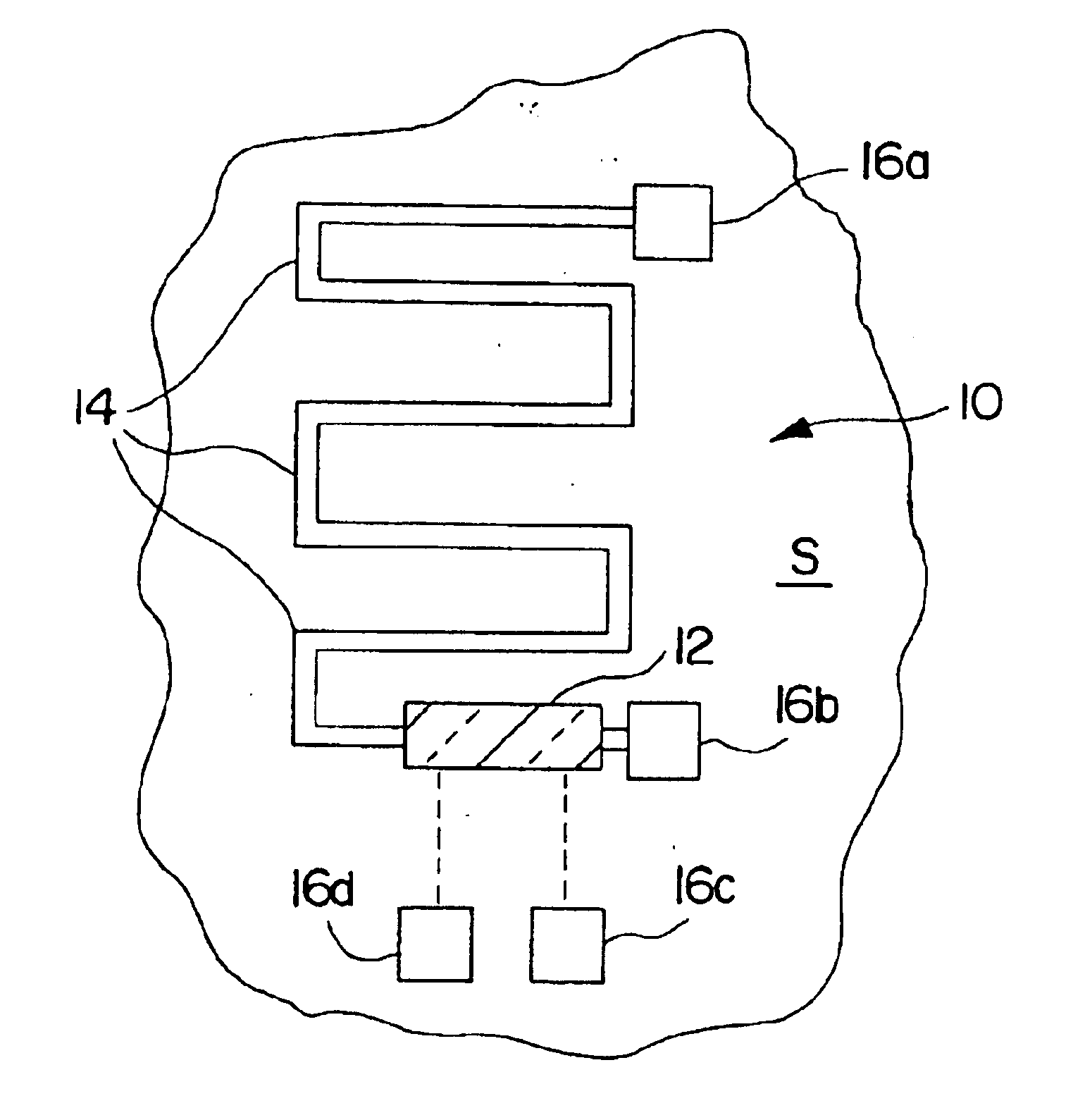
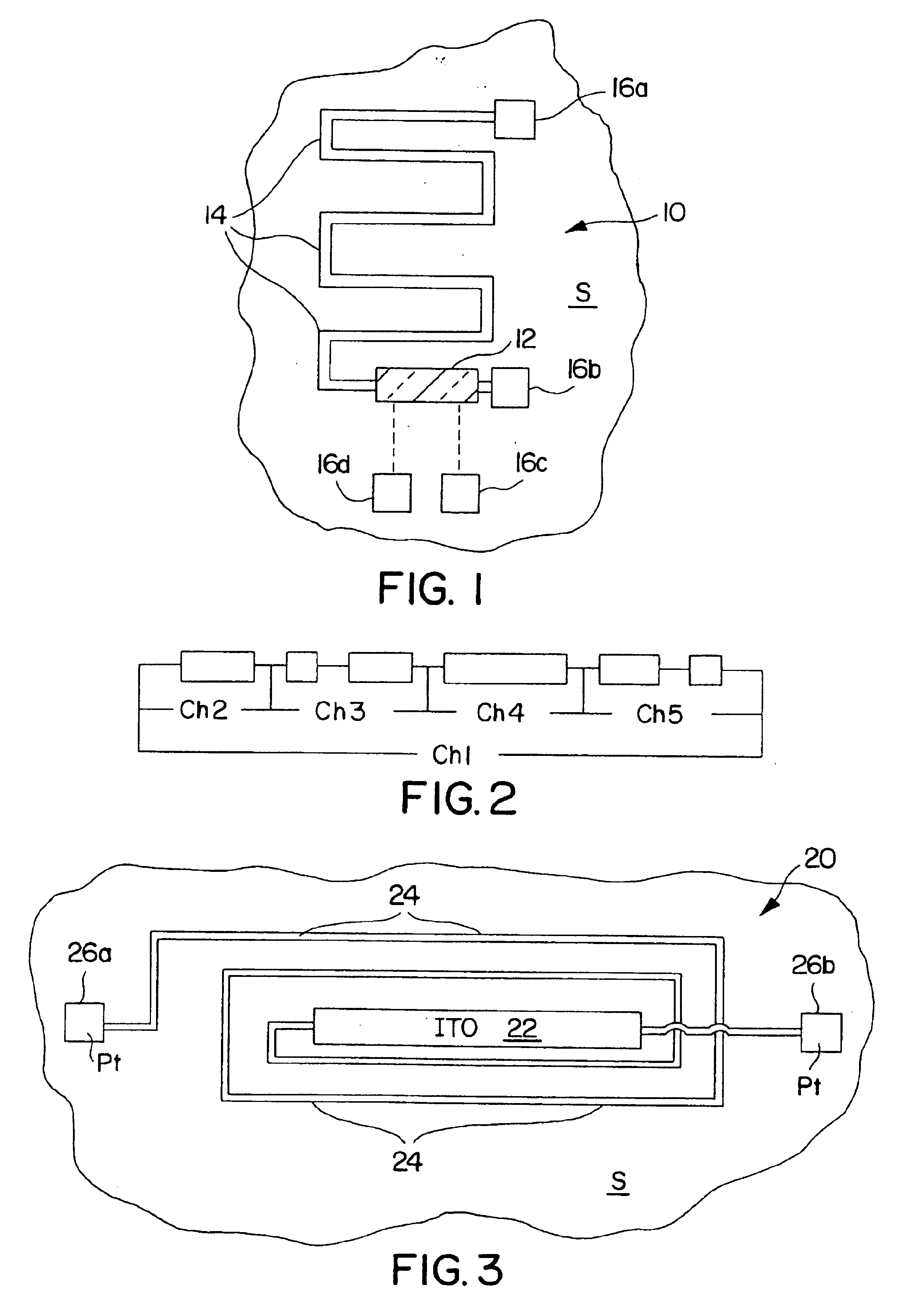
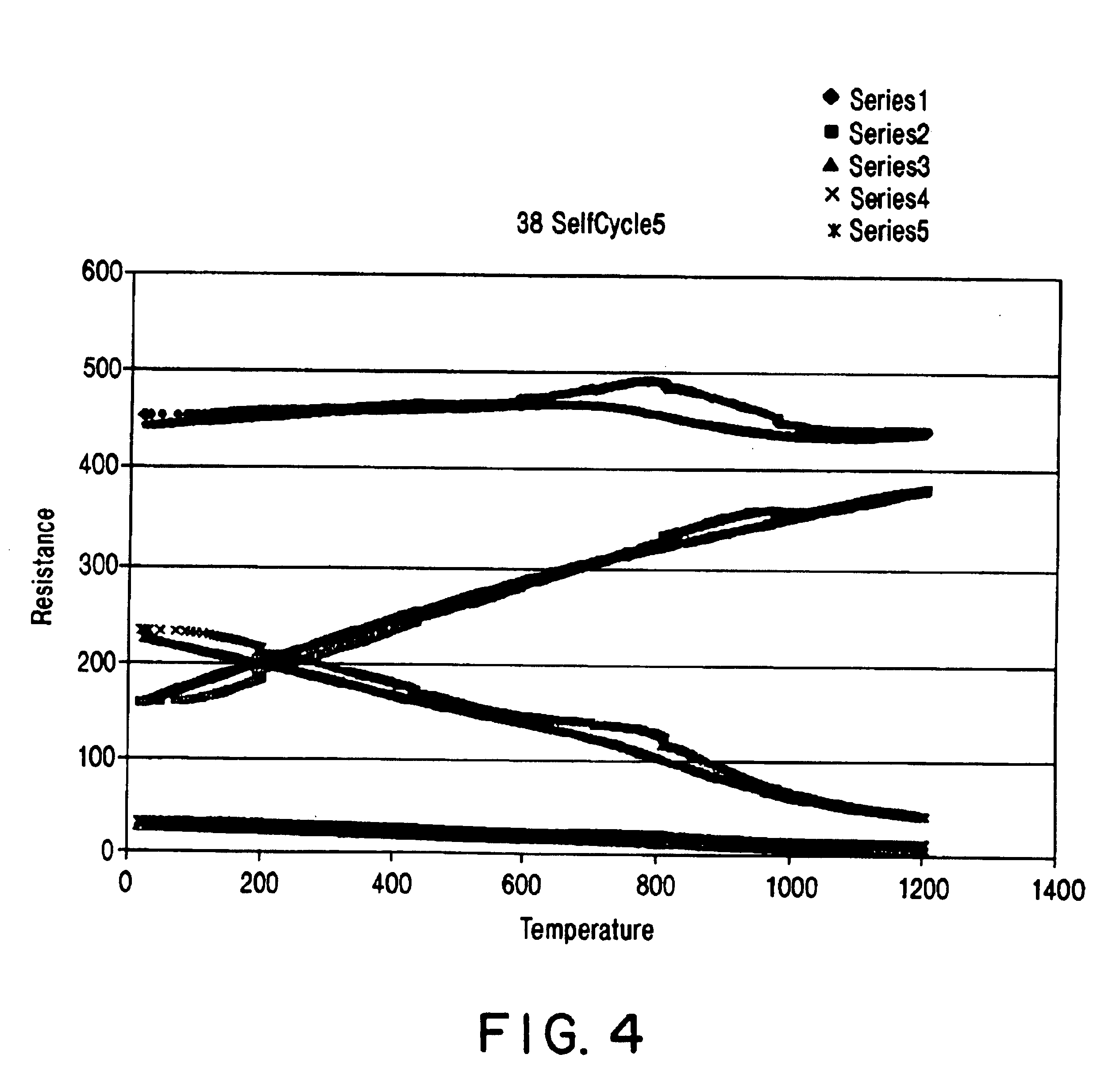
In the example, a four-wire method was used connecting to the bond pads 16. This method is well known to one skilled in the art. The sensor was fabricated and tested as outlined in the sections above. Four cycles of heating and cooling were measured, the results are shown below and in FIG. 4. After the first heating, the resistance changing with temperature is almost identical in four cycles, thus it shows the reproducibility is good.

TCR.sub.COMP =(R.sub.COMP,f -R.sub.COMP,0) / (R.sub.COMP,0 *.DELTA.T)=(437-442 / (437*1170)=-9.8(ppm / .degree. C.)

TCR.sub.Pt =(R.sub.Pt,f -R.sub.Pt,0) / (R.sub.Pt,0 *.DELTA.T)=(379-160) / (160*1170)=+1169(ppm / .degree. C.)

TCR.sub.ITO =(R.sub.ITO,f -R.sub.ITO,0) / (R.sub.ITO,0 *.DELTA.T)=(40-225) / (225*1170)=-702(ppm / .degree. C.)

Resistivity of Pt

At 30.degree. C.,

.rho..sub.Pt,0 =R.sub.Pt,0 *(w*t) / L=160*(0.6 mm*0.8.times.10.sup.-3) / 500=1.535.times.10.sup.-4 (.OMEGA.*m)

At 1200.degree. C.,

.rho..sub.Pt,f =R.sub.Pt,f *(w*t) / L=379*(0.6*0.8.times.10.sup.-3) / 500=3.639.times.1...


PUM

PropertyMeasurementUnit
thicknessaaaaaaaaaa
thicknessaaaaaaaaaa
diameteraaaaaaaaaa

Abstract

A self-compensated strain gage sensor having a temperature co-efficient of resistance (TCR) of essentially zero comprised of a wide band semiconductor and a compensating metal functioning as serial resistors. Based on the resistivity of the semiconductor and the metal and the temperature range in which the sensor will operate the dimensions of the semiconductor and the metal are determined to provide a zero TCR.

Description

1. Field of the InventionThe invention relates to thin film strain gages.2. Description of the Relevant ArtThe accurate measurement of both static and dynamic strain, at elevated temperatures is frequently required to determine the instabilities and life-times of various structural systems, and in particular, advanced aerospace propulsion systems. Conventional strain gages are typically applied to both stationary and rotating components for this purpose but are usually limited in scope due to their intrusive nature, severe temperature limitations and difficulties in bonding.Thin film strain sensors are particularly attractive in the gas turbine engine environment since they do not adversely effect the gas flow over the surface of a component and do not require adhesive or cements for bonding purposes. Typically, thin film strain gages are deposited directly onto the surface of a component by rf sputtering on other known thin film deposition technology and as a result are in direct c...

Claims


Application Information

Patent Timeline
Patent Type & Authority Patents(United States)
IPC IPC(8): G01L1/22G01L1/20H01C7/06
CPCG01L1/2281H01C7/06
Inventor GREGORY, OTTO J.
Owner BOARD OF GOVERNORS FOR HIGHER EDUCATION STATE OF RHODE ISLAND & PROVIDENCE PLANTATIONS
Why Eureka
Try Eureka