Propulsion system for a vertical and short takeoff and landing aircraft

a technology for propellant systems and aircraft, applied in vertical landing/take-off aircraft, aircraft navigation control, machines/engines, etc., can solve the problems of large diameter rotors, limited forward velocity, and compromise of most v/stol aircra

Inactive Publication Date: 2004-05-04
LOCKHEED MARTIN CORP
View PDF8 Cites 64 Cited by
  • Summary
  • Abstract
  • Description
  • Claims
  • Application Information

AI Technical Summary

Problems solved by technology

However, a helicopter, because of its very large diameter rotor, has a limited forward velocity, certainly not much over two hundred miles per hour.
Thus, most V / STOL aircraft are compromises.
As with a helicopter, the large fan provides significant thrust for vertical lift in hover, but its correspondingly large frontal area increases the drag of the aircraft and limits its maximum speed to subsonic speeds.
Consequently, the tandem fan concept is not an efficient design for a V / STOL aircraft.
The former concept severely limits the top speed of the aircraft, while the latter causes a severe weight penalty and requires a complex folding and storing system.
However, the use of a lift fan limits its placement within the aircraft, primarily to the fuselage and is unsuitable for use in multi-engine aircraft with the propulsion systems mounted on wing mounted nacelles.
In addition, in some applications the weight and / or "space" penalty associated with the use of a lift fan can not be tolerated in a single engine aircraft.

Method used


Image

  • Propulsion system for a vertical and short takeoff and landing aircraft
  • Propulsion system for a vertical and short takeoff and landing aircraft
  • Propulsion system for a vertical and short takeoff and landing aircraft

Examples


Embodiment Construction

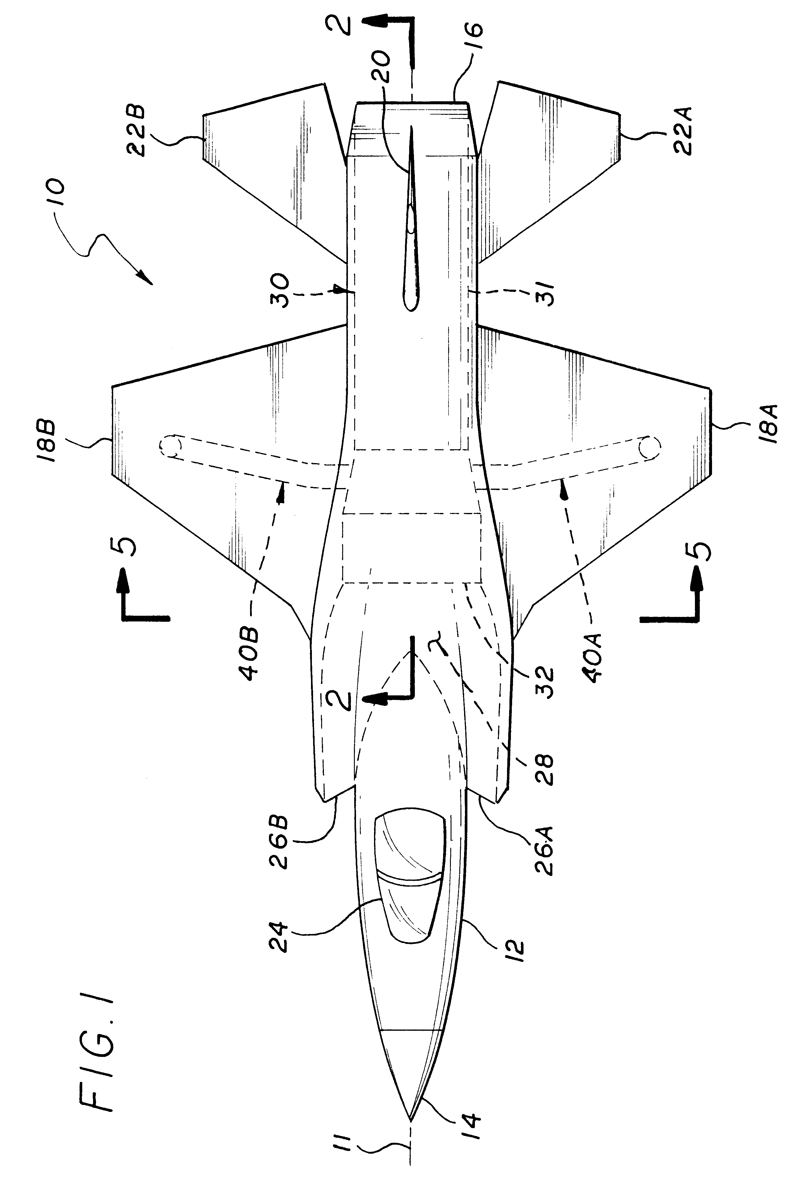
Illustrated in FIG. 1 is a single engine V / STOL type aircraft, generally indicated by numeral 10, having a longitudinal axis 11. The aircraft 10 includes a fuselage 12 with a nose 14, tail 16, wings 18A and 18B, vertical stabilizer 20, and horizontal stabilizers 22A and 22B. Other features include a cockpit 24, engine inlets 26A and 26B, which join to form an engine inlet duct 28. The subject propulsion system, generally indicated by numeral 30, includes a turbofan engine 31 having an inlet 32. Additionally illustrated are roll control assemblies, 40A and 40B, which are coupled to the engine 30 and exit to either side of fuselage 12 on the underside of the wings 18A and 18B, respectively. A further explanation of the function of the roll control nozzle assemblies 40A and 40B will be subsequently provided.

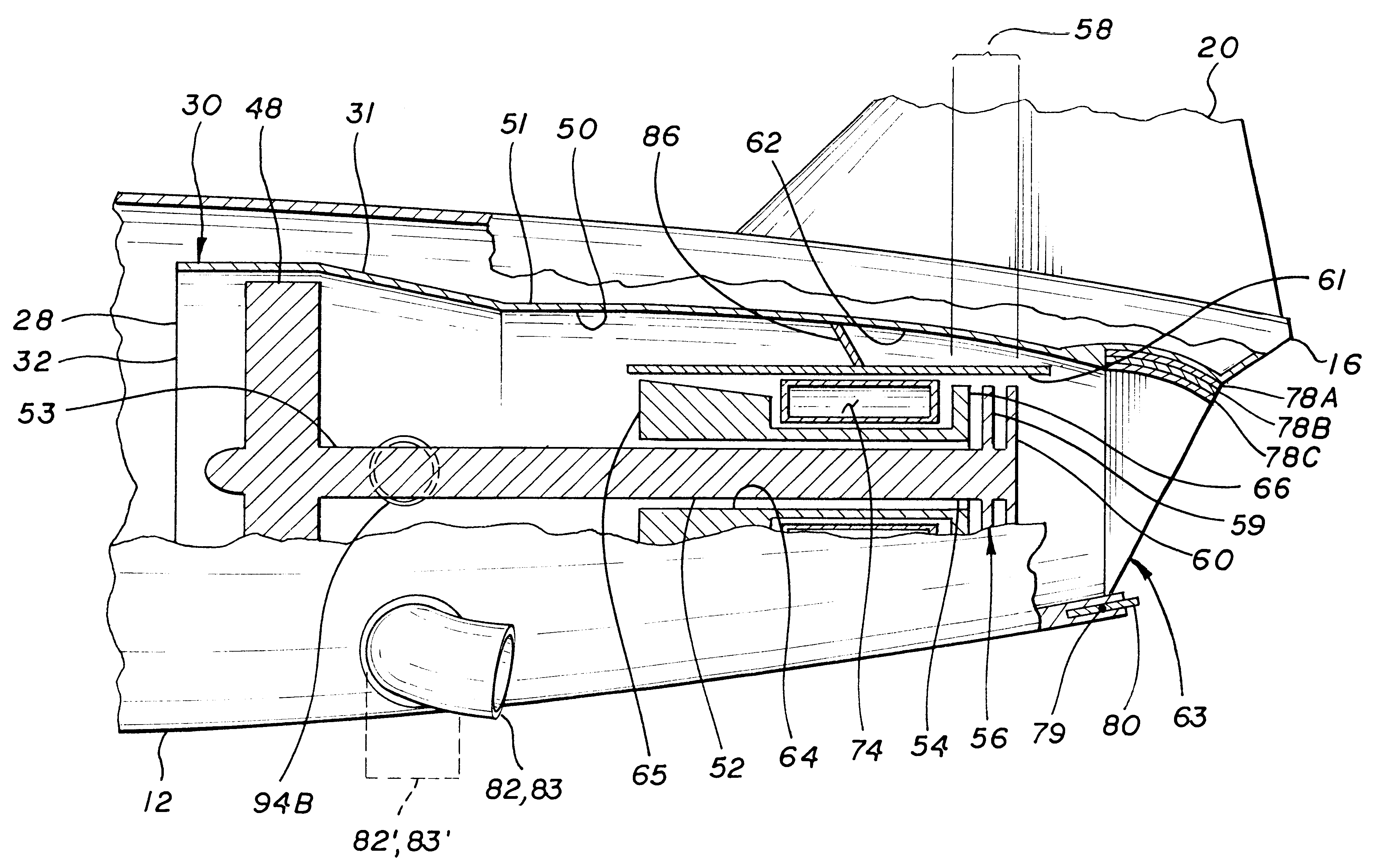
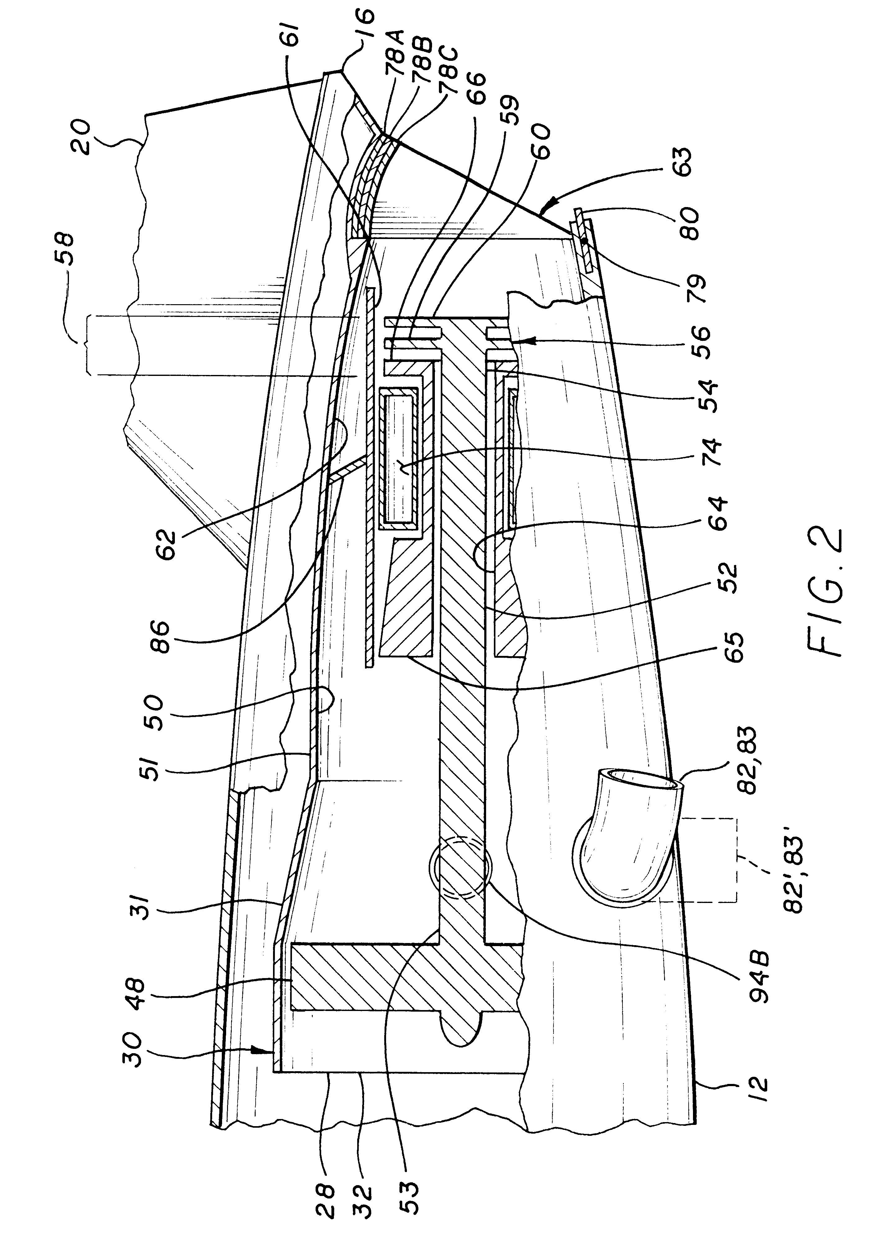
Illustrated in FIG. 2 is a partial cross-sectional view of the aircraft shown in FIG. 1 particularly illustrating the propulsion system 30. As previously stated, the propulsion syst...


PUM


Abstract

The invention is a propulsion system for a V / STOL aircraft. In detail, the invention includes a turbo-fan engine having a fan section with a variable pitch fan, a compressor section, a combustion section, a turbine section, said turbine section having a low-pressure turbine portion coupled to and driving the fan section and a high-pressure turbine portion coupled to and driving the compressor section. The engine further having a selectable operating point wherein a portion of the power generatable by the low-pressure turbine at a selected operating power setting is extracted to drive the fan section. A turbine outlet duct is included for directing the turbine section exhaust gases. A first angular shaped nozzle section is co-incident with the turbine outlet duct for directing exhaust from the fan section. A second nozzle section mounted to the first angular shaped nozzle section between the fan section and the compressor section. A system is included to shift said selectable operating point of said engine to a second operating point at the selected power setting increasing the power extracted by the low-pressure turbine portion of the turbine section; such that power extracted by the low-pressure turbine portion and applied to the fan section can be increased without changing the selected power setting and the pitch of the blades of the variable pitch fan section can be increased to absorb the increased power.

Description

1. Field of the InventionThe invention relates to the field of propulsion systems and, in particular, to a propulsion system for vertical and short takeoff and landing (V / STOL) aircraft.2. Description of Related ArtThe efficiency of a propulsion system for an aircraft increases as the exhaust velocity is reduced. Thus, during takeoff, landing and hovering, it is obvious that a helicopter, which provides a small incremental velocity to a large mass of air, is more efficient than a jet aircraft, which provides a large incremental velocity to a small mass of air. However, a helicopter, because of its very large diameter rotor, has a limited forward velocity, certainly not much over two hundred miles per hour. Thus, most V / STOL aircraft are compromises. For example, the AV-8A Harrier V / STOL aircraft utilizes a turbofan engine for both hover and cruise propulsion. As with a helicopter, the large fan provides significant thrust for vertical lift in hover, but its correspondingly large fro...

Claims


Application Information

Patent Timeline
Patent Type & Authority Patents(United States)
IPC IPC(8): B64D33/04B64C29/00B64D33/00F02K3/00F02K3/02F02K1/00
CPCB64C29/0066B64D33/04F02K1/006F02K3/025
Inventor BEVILAQUA, PAUL
Owner LOCKHEED MARTIN CORP
Why Eureka
Try Eureka