Crank angle detection apparatus

a detection apparatus and crank angle technology, applied in the direction of electric control, machines/engines, ignition safety means, etc., can solve the problems of inability to detect the rotational direction or reverse rotation of the engine, and inability to generate the reference crank angle signal for accurately controlling the fuel

Inactive Publication Date: 2004-05-11
MITSUBISHI ELECTRIC CORP
View PDF7 Cites 33 Cited by
  • Summary
  • Abstract
  • Description
  • Claims
  • Application Information

AI Technical Summary

Problems solved by technology

That is, it is impossible to generate the reference crank angle signal for accurately controlling the fuel injection, the ignition timing, etc., in accordance with the operating conditions of an internal combustion engine, and hence it is necessary to separately provide a crank angle detection sensor for generating a reference crank angle signal.
Furthermore, when the a

Method used


Image

  • Crank angle detection apparatus
  • Crank angle detection apparatus
  • Crank angle detection apparatus

Examples


first embodiment

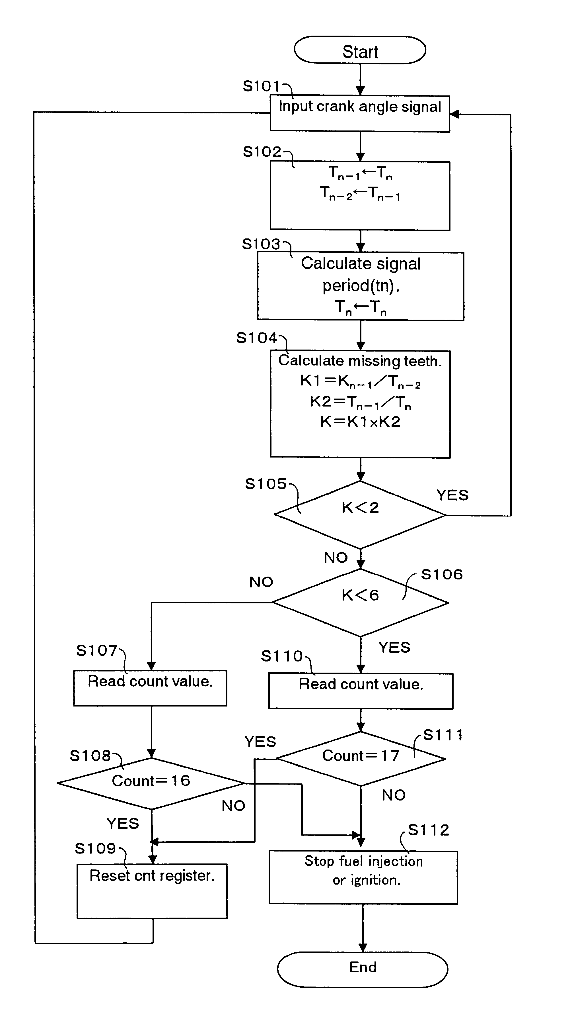
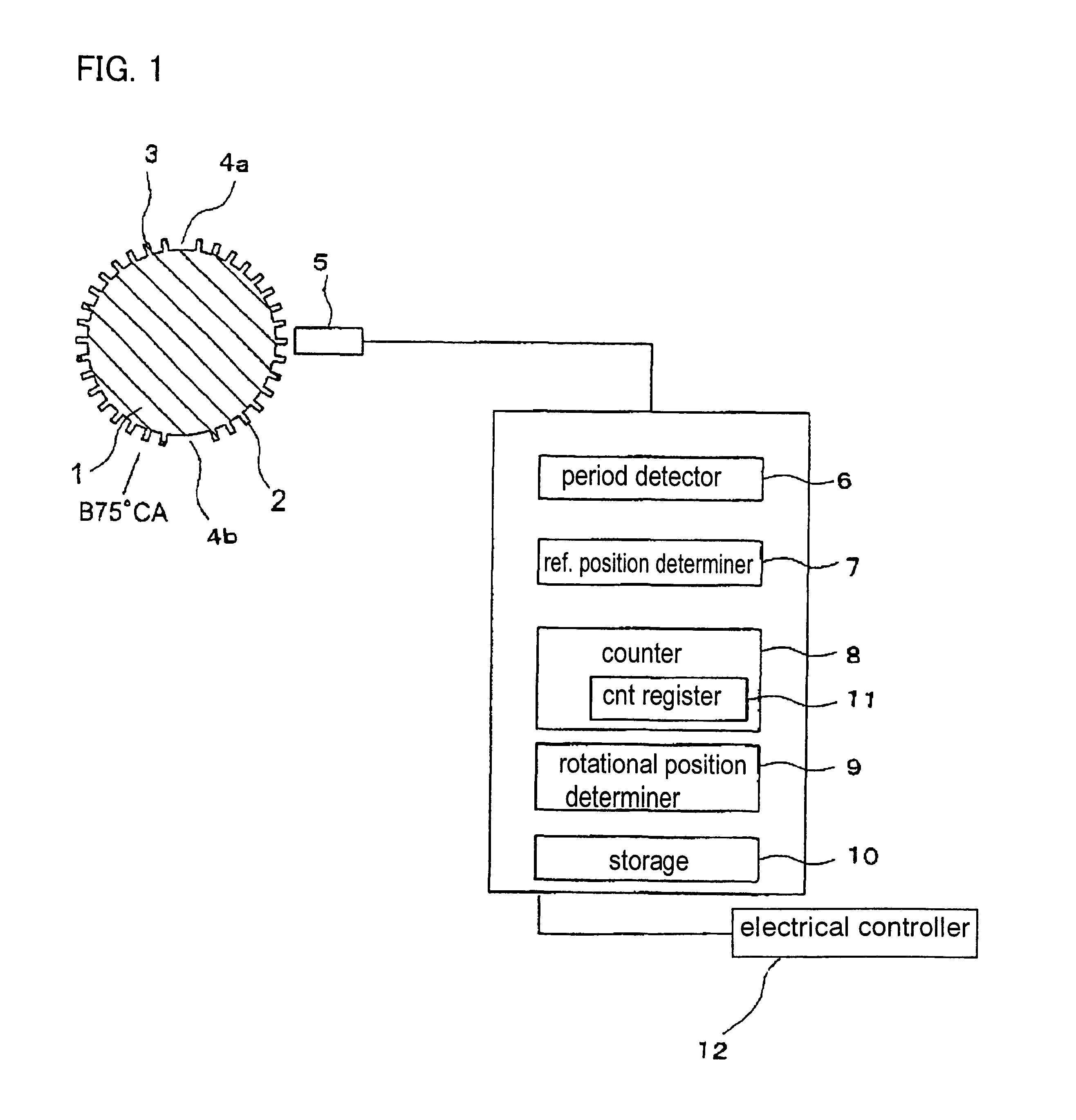
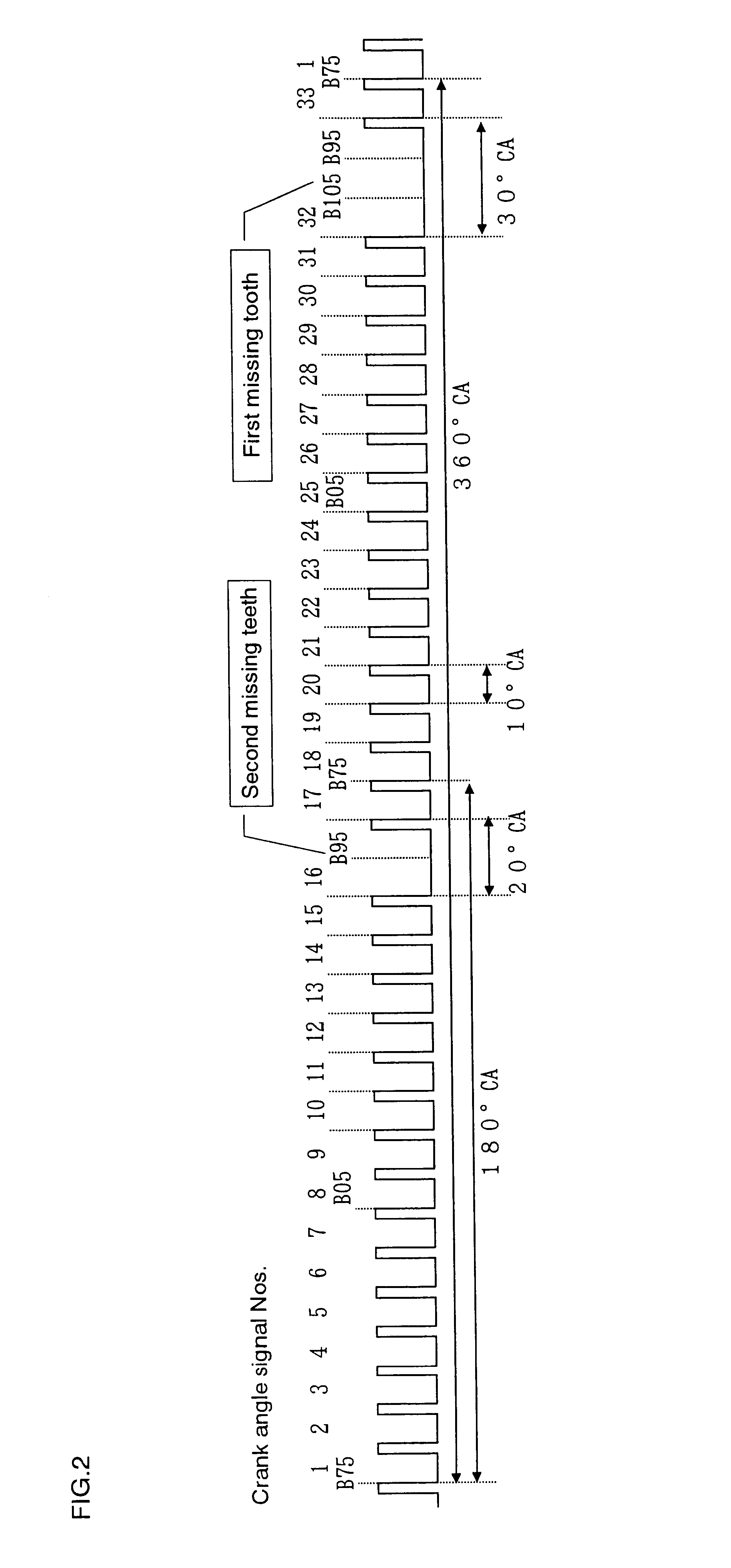
FIG. 1 shows the configuration of a crank angle detection apparatus for an internal combustion engine according to the present invention. FIG. 2 is a pattern chart of a crank angle signal generated by a crank angle sensor when the crankshaft of an internal combustion engine is caused to rotate. FIG. 3 is a flow chart for identifying the rotational direction of the crankshaft according to the crank angle detection apparatus of the first embodiment. FIG. 4 shows periods of the crank angle signal at respective calculation timing. FIG. 5 shows missing tooth determination values K at respective calculation timings. FIG. 6 and FIG. 7 show the count values at respective calculation timings when the crankshaft is rotating in the forward direction and when the crankshaft is rotating in the reverse direction, respectively. FIG. 7 indicates that the crank angle signal numbers are decreasing while the engine is rotating in the reverse direction. For instance, counting of crank angle signal puls...

embodiment 2

FIG. 8 shows the configuration of a crank angle detection apparatus according to a second embodiment of the present invention. This second embodiment is different from the above-mentioned first embodiment in the construction and function of a crank angle sensor, but is similar in other respects to the first embodiment. FIG. 9 shows a crank angle signal generated when the crankshaft of FIG. 8 is rotating in the forward direction, and FIG. 10 shows a crank angle signal generated when the crankshaft of FIG. 8 is rotating in the reverse direction. FIG. 11 is a graph illustrating the periods of the crank angle signals and the missing tooth determination values in the crank angle detection apparatus of the second embodiment. FIG. 12 shows a flow chart for determining the rotational direction of the crankshaft by means of the crank angle detection apparatus of FIG. 8.

A crank angle sensor 13 is provided with an element A 14 and an element B 15 which are arranged adjacent to the measurement ...

embodiment 3

FIG. 13 shows the configuration of a crank angle detection apparatus according to a third embodiment of the present invention. FIG. 14 shows missing tooth determination values of the crank angle detection apparatus of FIG. 13. FIG. 15 shows a flow chart of the operational process of the crank angle detection apparatus according to the third embodiment. In the third embodiment, a same crank angle sensor 13 as that of the above-mentioned second embodiment is used, and a measurement member 18 has a single reference position detection portion 19 alone. In addition, the crank angle detection apparatus includes a period detector or period detection part 6, a reference position determination part 7 and a rotational direction determination part 20.

When the reference position detection portion 19 passes the crank angle sensor 13 during the forward or reverse rotation of the crankshaft 1, the crank angle sensor 13 generates a crank angle signal as shown in FIG. 9 or a crank angle signal as sh...


PUM


Abstract

Even if the engine is started from any crank angle position, it is possible to correctly determine the rotational direction of a crankshaft, so that fuel injection or ignition can be stopped when the crankshaft is rotating in the reverse direction. A measurement member has a plurality of angular position detection portions arranged at equal intervals in a circumferential direction of the crankshaft and a plurality of reference position detection portions at which a part of the angular position detection portions is missing. A crank angle sensor is arranged near the measurement member for generating a crank angle signal representative of the rotational position of the crankshaft. A period detector detects periods of pulses of the crank angle signal. A reference position determiner determines a plurality of reference positions based on the signal periods. A counter counts the pulses of the crank angle signal. A rotational direction determiner detects the rotational direction of the crankshaft from the number of pulses counted between a plurality of reference positions.

Description

1. Field of the InventionThe present invention relates to a crank angle detection apparatus for detecting the crank angle of the crankshaft of an internal combustion engine, and more particularly, it relates to such a crank angle detection apparatus capable of identifying the rotational direction of the crankshaft.2. Description of the Related ArtConventionally, an apparatus for identifying the rotational direction of the crankshaft of an internal combustion engine has been proposed which includes: a first signal generating part and a second signal generating part that generate pulse signals in accordance with the rotational speeds or numbers of revolutions per minute of rotating elements, respectively, which are formed on their outer peripheries with a plurality of teeth arranged at equal intervals in their circumferential direction in such a manner that the signals generated by these signal generating parts become different from each other; a deviation part for obtaining a deviati...

Claims


Application Information

Patent Timeline
IPC IPC(8): F02D41/06F02D41/34F02D17/04F02P11/02F02D41/22F02D45/00
CPCF02D41/009F02D41/062F02D2250/06
Inventor KANAZAWA, EIJIYONEZAWA, SHIROMAKINO, TOMOKAZUWATANUKI, TAKUO
Owner MITSUBISHI ELECTRIC CORP
Why Eureka
Try Eureka