
Multicast communication device and method

a multicast communication and communication device technology, applied in the field of network systems, can solve the problems of inability to provide sufficiently efficient multicast transmission of multicast schemes, and the multicast route generated by the steps s705-s710 is not uniform

Inactive Publication Date: 2004-05-11
NEC CORP
View PDF10 Cites 84 Cited by
  • Summary
  • Abstract
  • Description
  • Claims
  • Application Information

AI Technical Summary

Benefits of technology

Another object of the present invention is to provide a multicast communication method and device which can change a multicast route rapidly and flexibly even in the case of the occurrence of a failure.
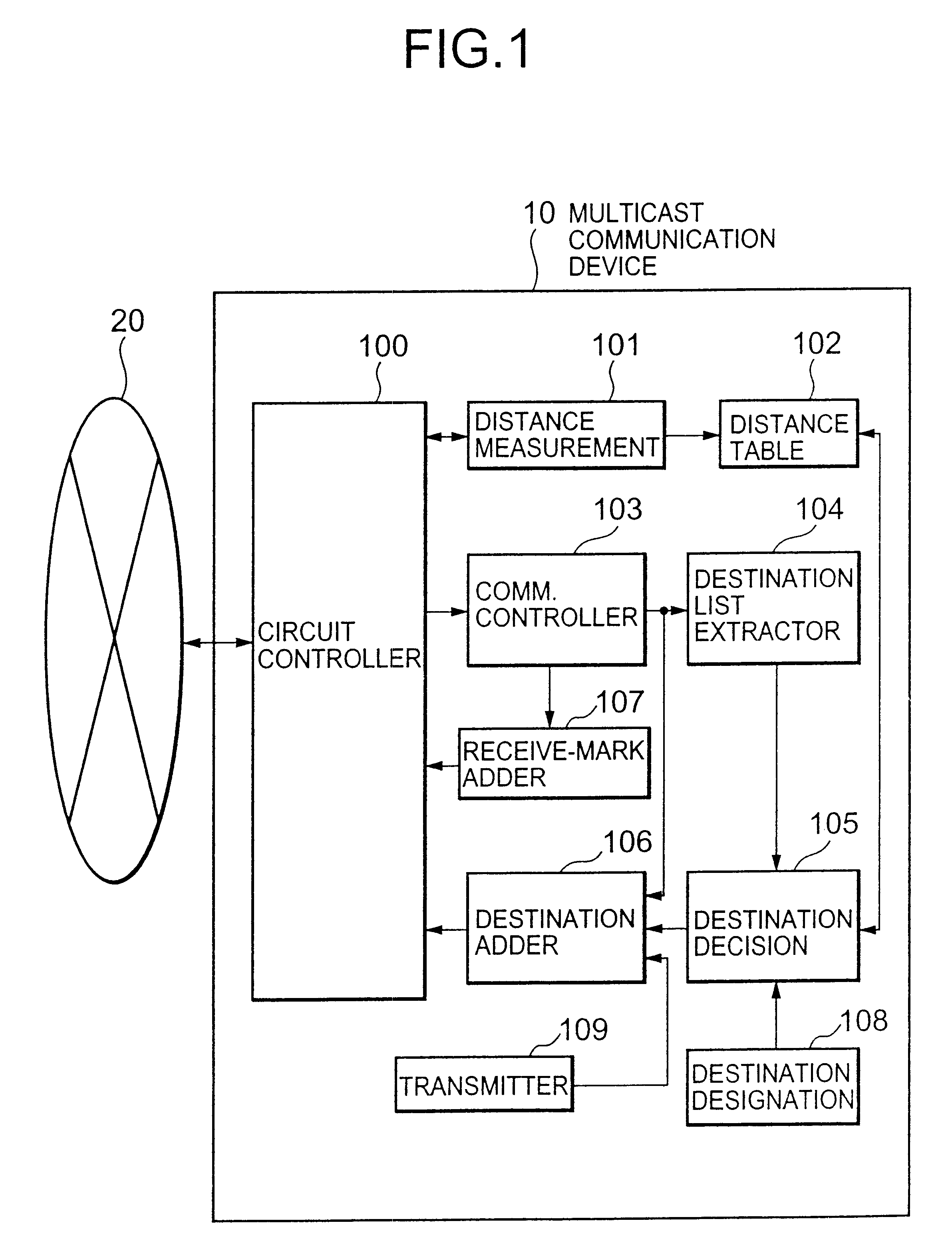
As described above, the multicast processing can be distributed among the nodes involved in the multicast route, resulting in reduced burden upon a source node. Further, since a plurality of nodes at the shortest distance can be selected as a next-hop node for multicast by referring to a distance table, the network can be efficiently used.

Problems solved by technology

However, the conventional transit multicast scheme cannot provide sufficiently efficient multicast transmission, especially when a failure occurs on the multicast route.
More specifically, the multicast route generated by the steps S705-S710 is not uniform.

Method used


Image

  • Multicast communication device and method
  • Multicast communication device and method
  • Multicast communication device and method

Examples


example-2

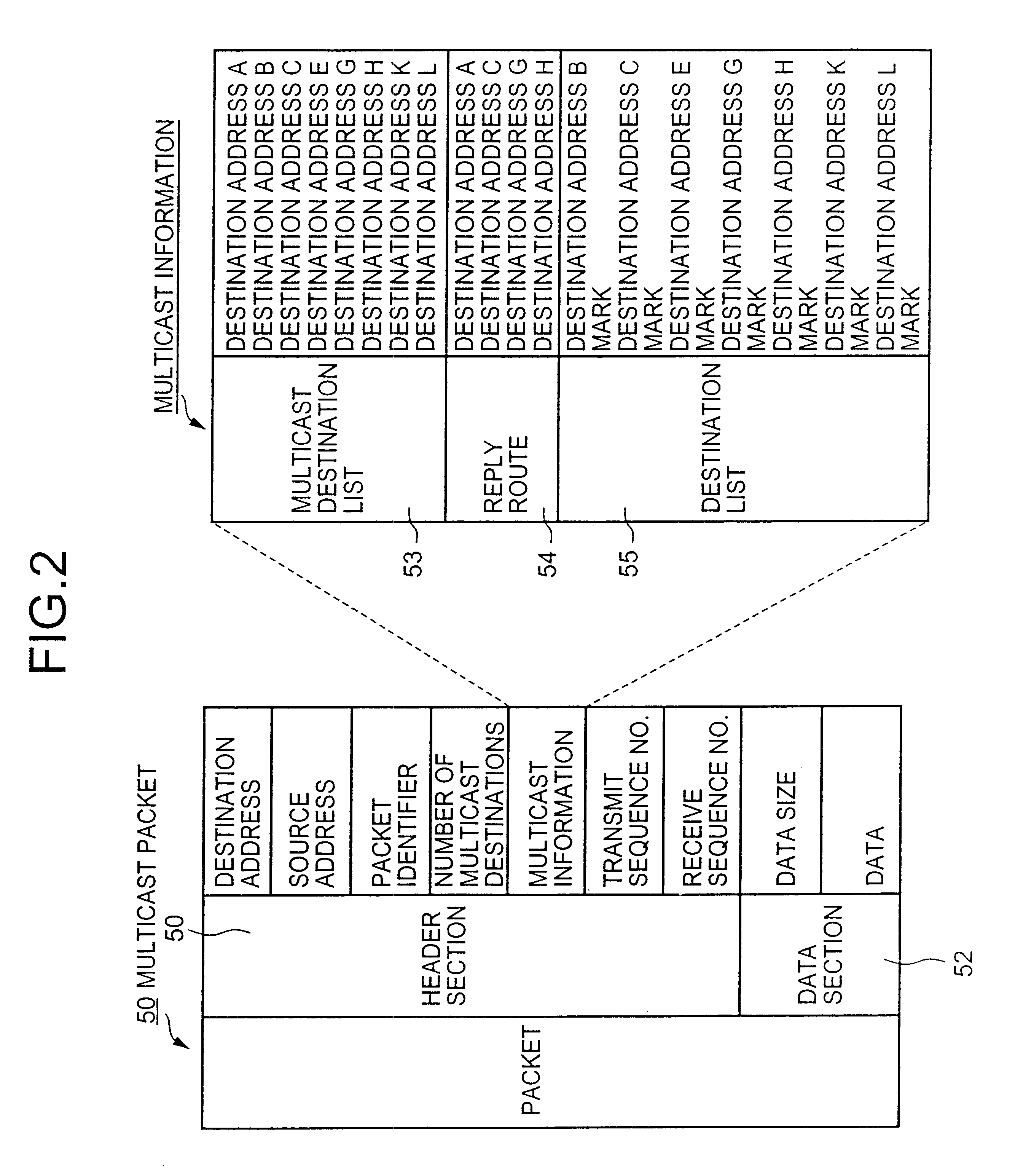
As shown in FIG. 10, consider the case where a failure occurs between the multicast communication devices G and L. In this case, the multicast communication device C, when receiving a multicast packet from the multicast communication device A, refers to the distance table of its own and selects the destination G having the shortest distance from the destinations G, H, K, and L conveyed by the received multicast packet. Further, the multicast communication device C refers to the distance table of the multicast communication device G and selects the destinations H and K having the shortest distance from the destinations H, K, and L, and then selects the destination L by referring to the distance table of the multicast communication device H. In this way, the multicast routes determined by the multicast communication device C are generated as follows (see FIG. 10):

e) C.fwdarw.G.fwdarw.H.fwdarw.L; and

f) C.fwdarw.G.fwdarw.K.

It is the same with the multicast communication device G which h...

example-3

After the multicast communication device A determines the multicast routes A.fwdarw.B and A.fwdarw.C, the respective groups of the multicast communication devices B and C are produced as mentioned above. In the grouping process, if the grouping of the multicast communication device C is performed before that of the multicast communication device B, then the multicast communication device E belongs to the group of the grouping of the multicast communication device C.

As shown in FIG. 11, therefore, the multicast routes are generated as follow:

i) A.fwdarw.C.fwdarw.E;

j) A.fwdarw.C.fwdarw.G.fwdarw.H;

k) A.fwdarw.C.fwdarw.G.fwdarw.K;

l) A.fwdarw.C.fwdarw.G.fwdarw.L; and

m) A.fwdarw.B.

It should be noted again that only multicast routes, A.fwdarw.B and A.fwdarw.C, are determined at this stage and the following routes to E, G, H, K and L are not determined but generated by grouping under B and C. The respective multicast communication devices downstream from the multicast communication device A...


PUM


Abstract

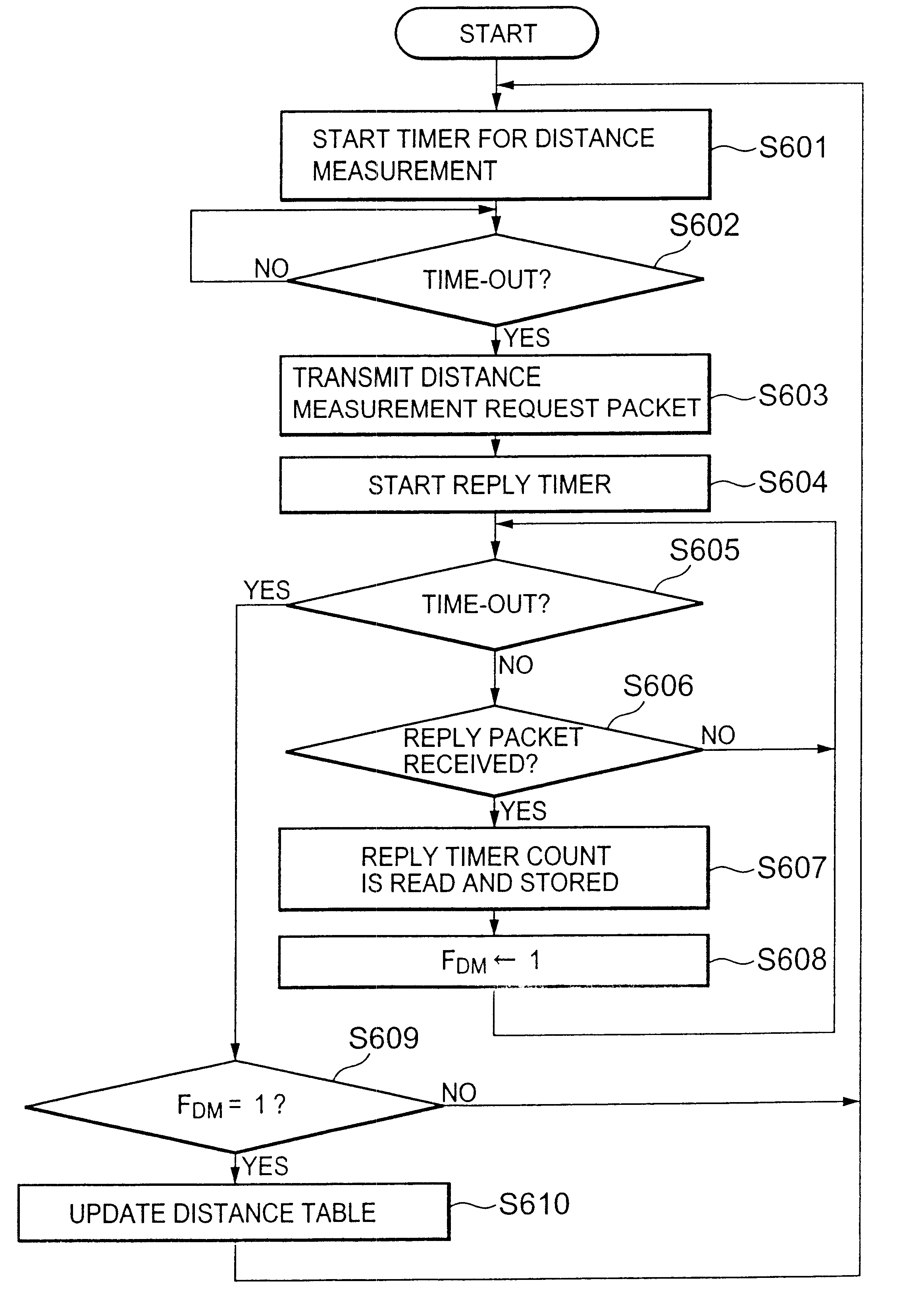
In a multicast communication network, each of the nodes stores a table containing distances between each of the multicast communication nodes and the other multicast communication nodes. When receiving a destination list, the node sequentially selects a node having a shortest distance from the destination list by referring to the table to generate a multicast route. Communication is made through the multicast route.

Description

1. Field of the InventionThe present invention relates to a network system composed of a plurality of nodes and, particularly, to a system and method for multicast communication between a source node and a plurality of destination nodes.2. Description of the Prior ArtIn a multicast network, blocks of information such as packets are multicast from a source node to a plurality of destination nodes. As a multicast scheme, a multiple access multicast scheme and a transit multicast scheme are known. According to the multiple access multicast scheme, the source node sequentially communicates with the destination nodes to repeatedly transmit the same packet to the destination nodes. According to the transit multicast scheme, the packets are transferred from the source node to one of the destination nodes and then are successively transferred to the other destination nodes.As a conventional transit multicast scheme, Japanese Patent Application Laid-Open No. 8-256177 discloses a mail multica...

Claims


Application Information

Patent Timeline
IPC IPC(8): H04L12/56H04L12/18H04L12/28H04B7/15H04L45/16H04M11/00
CPCH04L12/1854H04L45/12H04L45/122H04L45/16H04L12/1868
Inventor SUZUKI, MITSUTAKA
Owner NEC CORP
Learn More