Drying apparatus

a technology of drying apparatus and drying chamber, which is applied in the direction of drying machines with progressive movements, photosensitive materials, instruments, etc., can solve the problems of increasing the weight and the length reducing the efficiency of the drying apparatus, and expensive explosion proof equipment to ensure safety

Inactive Publication Date: 2004-05-18
FUJIFILM CORP +1
View PDF7 Cites 10 Cited by
  • Summary
  • Abstract
  • Description
  • Claims
  • Application Information

AI Technical Summary

Benefits of technology

The plurality of exhaust ducts having the inlets at the different positions in the drying chamber are provided to form the independent exhaust passage comprising the duct for circulating the exhaust gas to the circulation blower, and the duct for directly feeding the exhaust gas to the joining duct. This configuration allows the exhaust duct having the inlet in the lowest gas concentration area to be used as a duct for the exhaust gas circulated to the circulation blower, and allows the exhaust duct having the inlet in a high gas concentration area to be used as a duct for the exhaust gas directly fed to the joining duct. This prevents the exhaust gas with the high gas concentration from being introduced into the circulation blower. Therefore, the gas concentration in the circulation blower to be an ignition source in view of explosion proofing safety can be kept lower than the lower explosive level with a simple apparatus configuration.

Problems solved by technology

If the gas concentration cannot be kept lower than the lower explosive level, expensive explosion proof equipment must be provided to secure safety.
This reduces efficiency of the drying apparatus to require a complex device that can set the amount of supplied and exhausted air for each drying zone, thus increasing the weight and the length of the drying apparatus.
However, in the conventional drying apparatus in Japanese Utility Model Publication No. 6-28221, when the organic solvent rapidly evaporates in one of the plurality of drying zones, an exhaust gas with an extremely high gas concentration is circulated to the circulation blower, which may cause a dangerous operating condition in view of explosion proofing without a large amount of fresh air mixed by a main supply blower.
As a result, a main supply blower and a circulation blower having a large capacity must be provided to increase equipment costs and running costs.

Method used


Image

  • Drying apparatus
  • Drying apparatus
  • Drying apparatus

Examples


Embodiment Construction

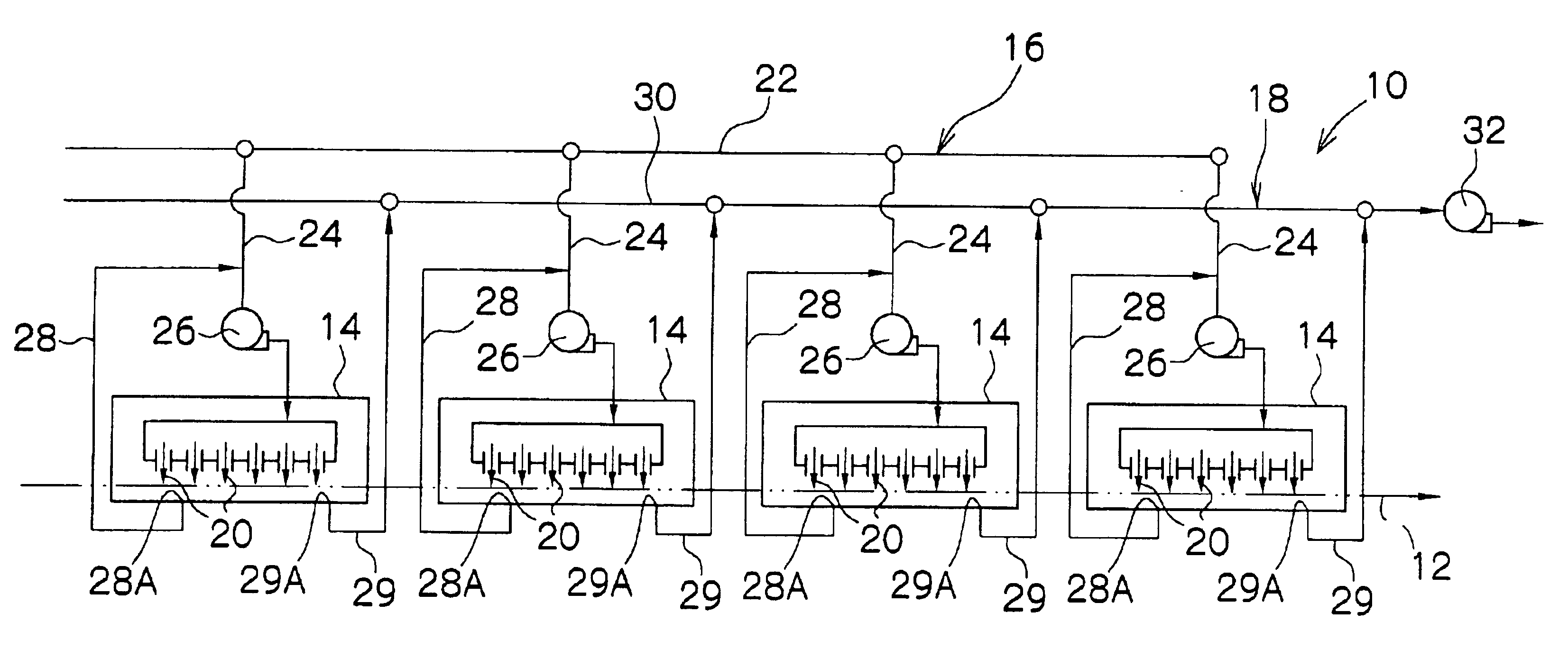
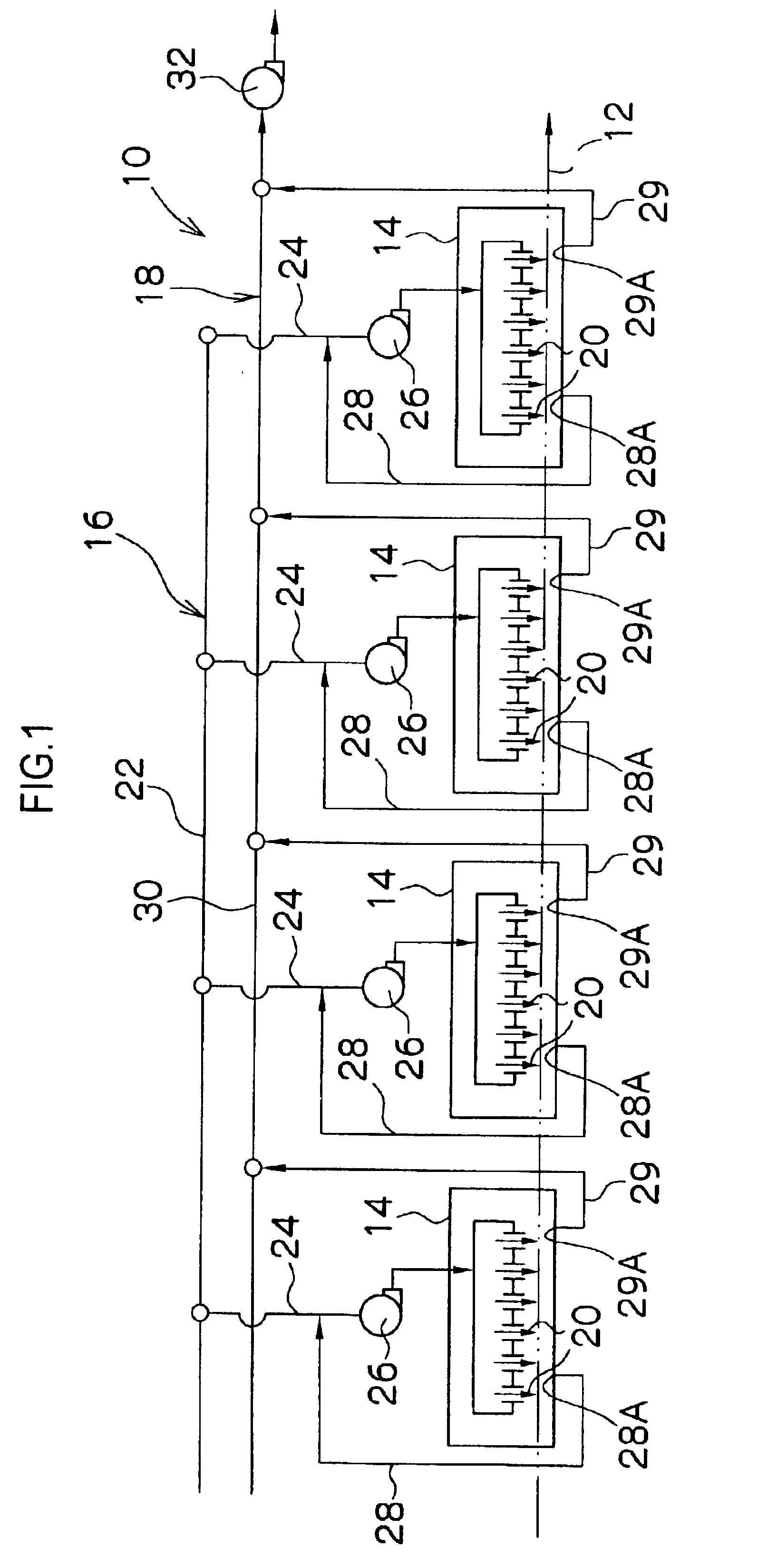
An example will be described in which an intermediate web of a magnetic recording medium with a magnetic coating liquid of composition shown in Table 1 applied on the web is dried by the drying apparatus in FIG. 1. A drying apparatus including an exhaust system that distributes an exhaust gas from one exhaust duct provided in a drying chamber to a circulation blower and a joining duct was used for comparison.

Then, gas concentrations of exhaust gases introduced into the circulation blower were examined in the example and a comparative example.

The coating liquid in Table 1 was applied on a web made of PET (polyethylene terephthalate) of 9 .mu.m thick and 550 mm wide to form a 2.5 .mu.m thick dry film at a coating speed of 200 m / min.

Drying conditions in the drying apparatus in both the example and the comparative example were a total amount of exhaust air of 120 N / m.sup.3, an amount of supply air for each drying chamber of 30 N / m.sup.3 (a total amount of four drying chambers of 120 N / m...


PUM


Abstract

A concentration of a gas introduced into a circulation blower and an exhaust blower is reduced with a simple apparatus configuration. In an exhaust system, exhaust gases from a plurality of drying chambers are joined to a joining duct to be then exhausted by an exhaust blower. A plurality of exhaust ducts having inlets at different positions in each drying chamber are provided, and the exhaust duct having the inlet in the lowest gas concentration area is used as a duct for an exhaust gas circulated to a circulation blower.

Description

1. Field of the InventionThe present invention relates to a drying apparatus and, more particularly, to a drying apparatus for an organic solvent that is used for manufacturing a photosensitive material or a magnetic recording medium.2. Description of the Related ArtGenerally, photosensitive materials and magnetic recording media are manufactured through a drying process after a predetermined coating liquid such as a magnetic liquid is applied on a continuously traveling support (hereinafter referred to as a web), so that an organic solvent in the coating liquid is evaporated by a drying apparatus to dry the coating liquid.Such a drying apparatus for an organic solvent requires that an organic solvent concentration (hereinafter referred to as a gas concentration) of an exhaust gas containing the organic solvent is kept sufficiently lower than a lower explosive level (LEL). If the gas concentration cannot be kept lower than the lower explosive level, expensive explosion proof equipme...

Claims


Application Information

Patent Timeline
Patent Type & Authority Patents(United States)
IPC IPC(8): F26B21/02F26B21/04F26B13/10F26B25/00G03D15/02
CPCF26B13/10F26B21/04F26B25/009G03D15/022
Inventor TAKAHASHI, SHINSUKE
Owner FUJIFILM CORP
Why Eureka
Try Eureka