Drying apparatus

a technology of drying apparatus and drying chamber, which is applied in the direction of drying machines with progressive movements, photosensitive materials, instruments, etc., can solve the problems of increasing the weight and the length reducing the efficiency of the drying apparatus, and expensive explosion proof equipment to ensure safety

Inactive Publication Date: 2003-05-01
FUJIFILM CORP +1
View PDF0 Cites 8 Cited by
  • Summary
  • Abstract
  • Description
  • Claims
  • Application Information

AI Technical Summary

Problems solved by technology

If the gas concentration cannot be kept lower than the lower explosive level, expensive explosion proof equipment must be provided to secure safety.
This reduces efficiency of the drying apparatus to require a complex device that can set the amount of supplied and exhausted air for each drying zone, thus increasing the weight and the length of the drying apparatus.
However, in the conventional drying apparatus in Japanese Utility Model Publication No. 6-28221, when

Method used


Image

  • Drying apparatus
  • Drying apparatus
  • Drying apparatus

Examples


Embodiment Construction

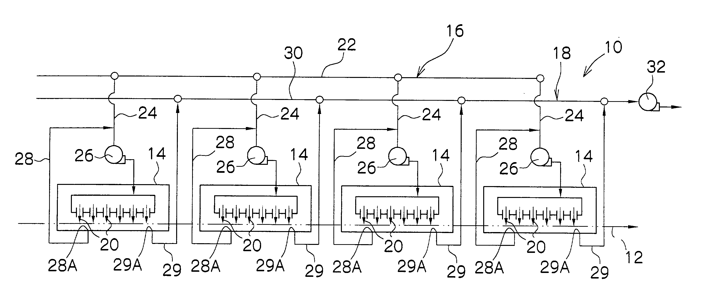
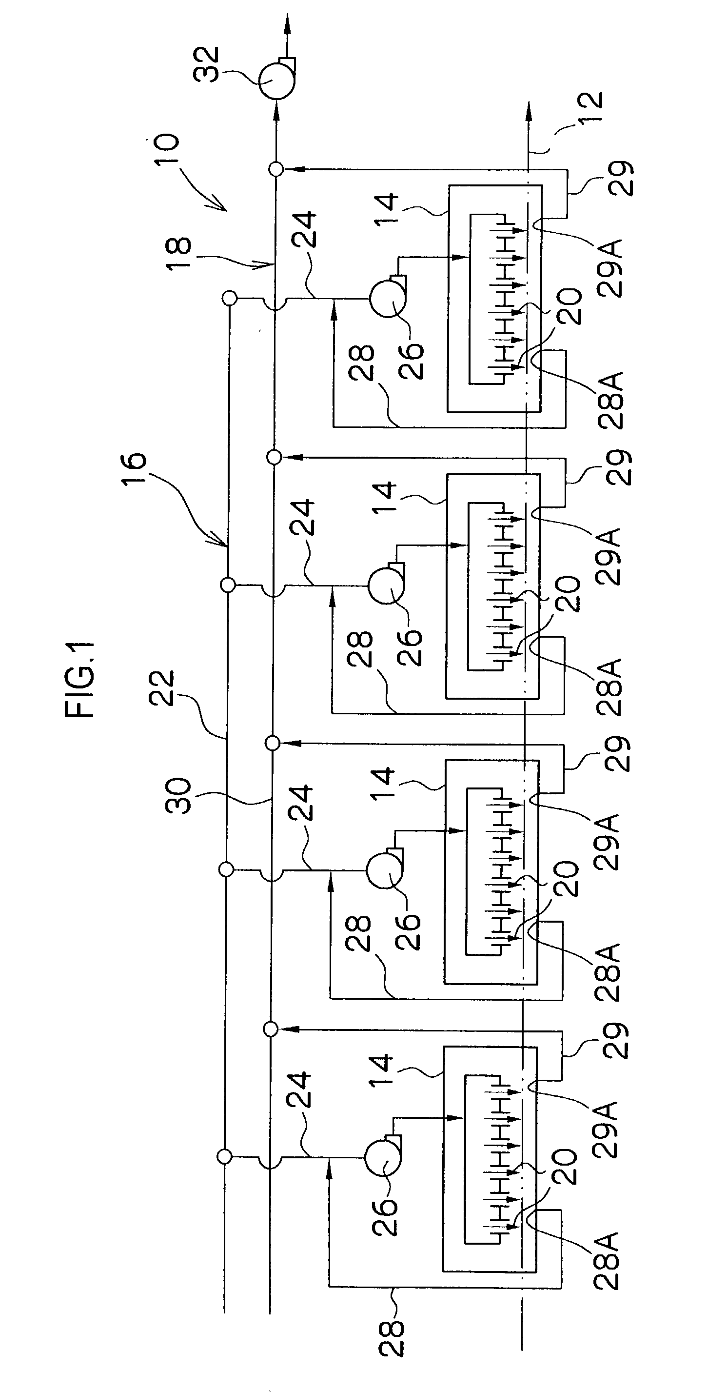
[0036] An example will be described in which an intermediate web of a magnetic recording medium with a magnetic coating liquid of composition shown in Table 1 applied on the web is dried by the drying apparatus in FIG. 1. A drying apparatus including an exhaust system that distributes an exhaust gas from one exhaust duct provided in a drying chamber to a circulation blower and a joining duct was used for comparison.

[0037] Then, gas concentrations of exhaust gases introduced into the circulation blower were examined in the example and a comparative example.

[0038] The coating liquid in Table 1 was applied on a web made of PET (polyethylene terephthalate) of 9 .mu.m thick and 550 mm wide to form a 2.5 .mu.m thick dry film at a coating speed of 200 m / min.

1 TABLE 1 Part by Composition of coating liquid weight Ferromagnetic metal fine powder 100 (Composition Fe:Zn:Ni = 92:4:4) (Hc2000 Oe, BET surface area ratio 58 m.sup.2 / g, acicular ratio 5.0) Vinyl chloride-vinyl acetate copolymer 12 (d...


PUM


Abstract

A concentration of a gas introduced into a circulation blower and an exhaust blower is reduced with a simple apparatus configuration. In an exhaust system, exhaust gases from a plurality of drying chambers are joined to a joining duct to be then exhausted by an exhaust blower. A plurality of exhaust ducts having inlets at different positions in each drying chamber are provided, and the exhaust duct having the inlet in the lowest gas concentration area is used as a duct for an exhaust gas circulated to a circulation blower.

Description

[0001] 1. Field of the Invention[0002] The present invention relates to a drying apparatus and, more particularly, to a drying apparatus for an organic solvent that is used for manufacturing a photosensitive material or a magnetic recording medium.[0003] 2. Description of the Related Art[0004] Generally, photosensitive materials and magnetic recording media are manufactured through a drying process after a predetermined coating liquid such as a magnetic liquid is applied on a continuously traveling support (hereinafter referred to as a web), so that an organic solvent in the coating liquid is evaporated by a drying apparatus to dry the coating liquid.[0005] Such a drying apparatus for an organic solvent requires that an organic solvent concentration (hereinafter referred to as a gas concentration) of an exhaust gas containing the organic solvent is kept sufficiently lower than a lower explosive level (LEL). If the gas concentration cannot be kept lower than the lower explosive level...

Claims


Application Information

Patent Timeline
IPC IPC(8): F26B13/10F26B21/04F26B25/00G03D15/02
CPCF26B13/10G03D15/022F26B25/009F26B21/04
Inventor TAKAHASHI, SHINSUKE
Owner FUJIFILM CORP
Why Eureka
Try Eureka