System for management of fuel in a cold start fuel passageway

a technology of cold start fuel and management system, which is applied in the direction of machines/engines, combustion air/fuel air treatment, electric control, etc., can solve the problems of fuel or fuel vapor, and achieve the effect of dissipating fuel vapor, reducing or completely eliminating the possibility of engine backfiring, and delay in the initiation of the spark ignition system

Inactive Publication Date: 2004-05-18
HITACHI LTD
View PDF21 Cites 17 Cited by
  • Summary
  • Abstract
  • Description
  • Claims
  • Application Information

AI Technical Summary

Benefits of technology

In the event that the ECU determines the probability of fuel within the cold start fuel passageway, the present invention provides a number of different procedures programmed in the ECU designed to dissipate the fuel from the cold start fuel passageway. These procedures minimize the creation of noxious emissions and hydrocarbons and even prevent possible backfiring of the internal combustion engine.
In yet a further procedure to dissipate fuel vapors present within the cold start fuel passageway, the ECU delays the initiation of the spark ignition system for the engine for a few revolutions upon a subsequent engine start up condition. Such delay in the initiation of the spark system ensures that fuel vapors contained within the cold start fuel passageway are inducted to the engine combustion chambers. Such delay in the initiation of the spark ignition system also reduces or completely eliminates the possibility of backfiring of the engine. Additionally, preferably the throttle is in a closed position while dissipating the vapors from the cold start fuel passageway so that the air inducted by the rotation of the engine passes through the cold start fuel passageway.

Problems solved by technology

If not, indicative of a heater malfunction, there is a probability of fuel or fuel vapors in the cold start passageway upon a subsequent use of the cold start system upon the next engine start up.

Method used


Image

  • System for management of fuel in a cold start fuel passageway
  • System for management of fuel in a cold start fuel passageway
  • System for management of fuel in a cold start fuel passageway

Examples


Embodiment Construction

Embodiments of the Present Invention

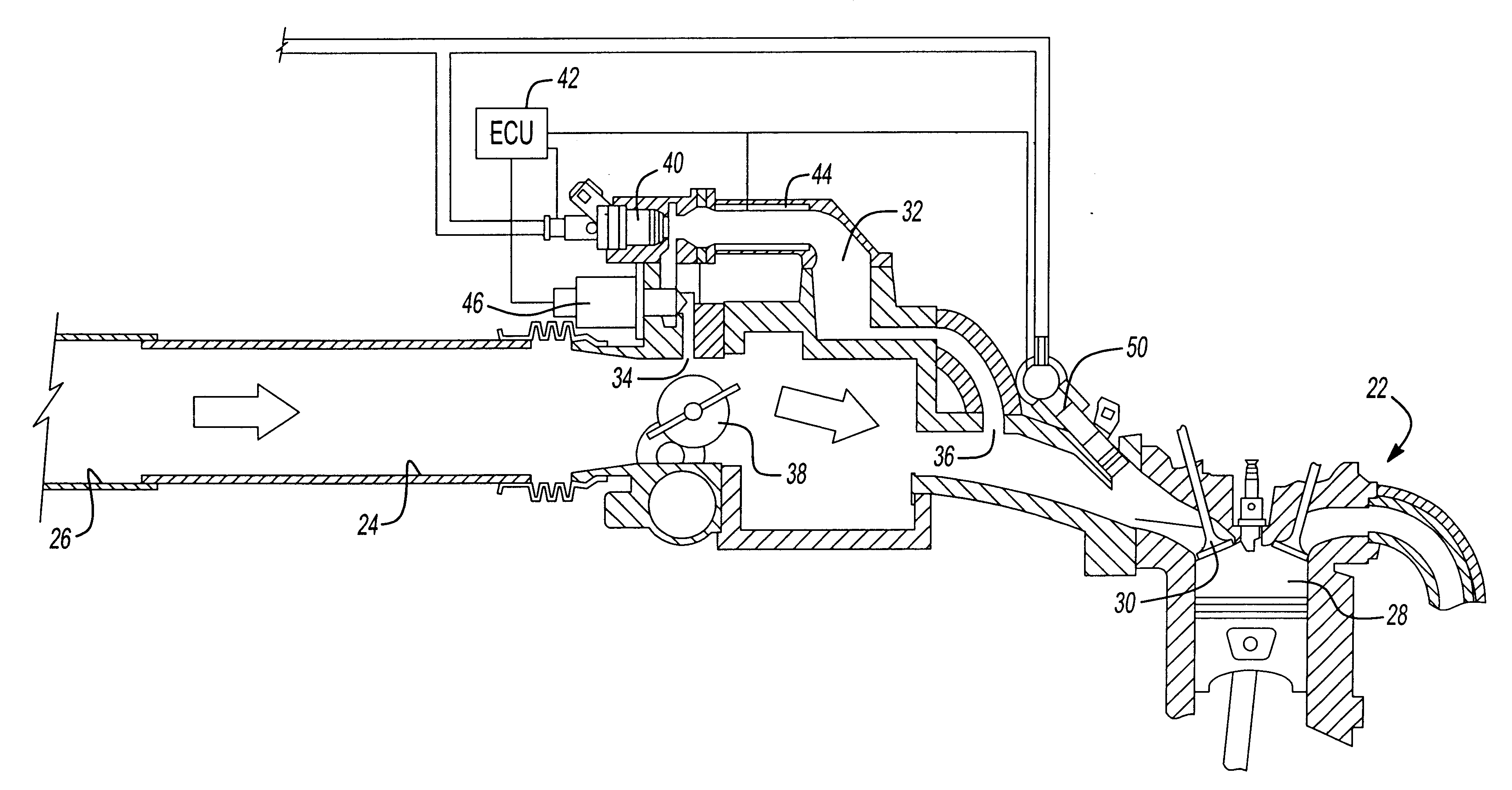
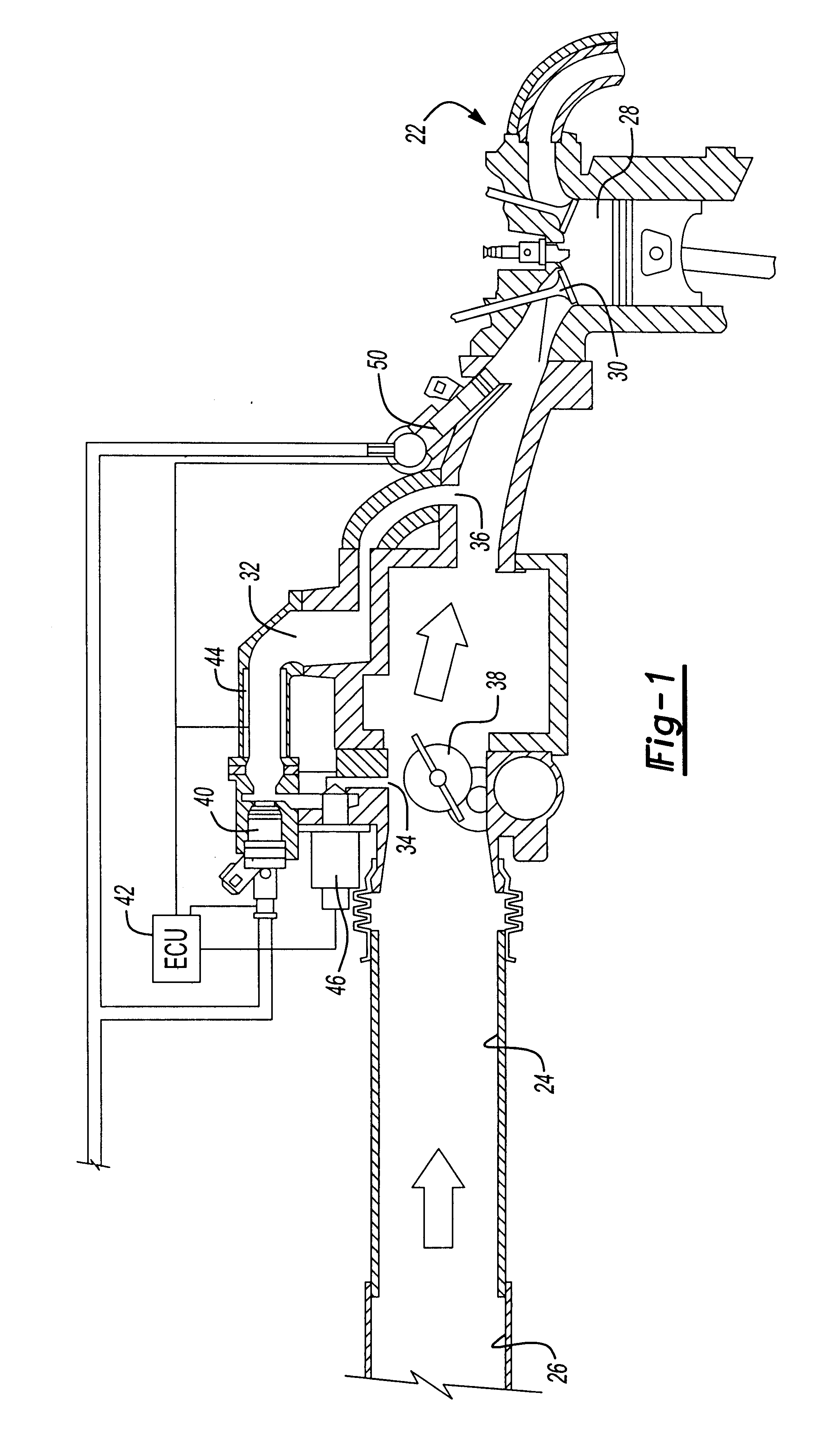
With reference first to FIG. 1, a fuel delivery system 20 is there illustrated for use with an internal combustion engine 22 (illustrated only diagrammatically). The internal combustion engine 22 includes an intake manifold 24 having an intake end 26 into which air is inducted. The intake manifold 24, in the conventional fashion, fluidly connects the intake end 26 to one or more internal combustion chambers 28 of the internal combustion engine 22 through an intake valve 30.

Still referring to FIG. 1, a cold start fuel passageway 32 has its inlet end 34 open to the intake manifold 24. Similarly, the cold start fuel passageway 32 has an outlet end 36 which is also open to the intake manifold 24 but downstream from its inlet 34.

A throttle valve 38, which is preferably an electronically controlled valve, is operatively positioned within the intake manifold 24. The throttle valve 38 is movable between a closed position, in which the throttle valve 38 su...


PUM


Abstract

A system for the management of fuel and fuel vapors in the cold start fuel passageway of an internal combustion engine which has a cold start fuel injector which, when activated, introduces fuel into the cold start fuel passageway. The system includes an engine control unit (ECU) which determines the probability of fuel within the cold start passageway. Different procedures programmed in the ECU are then utilized to dissipate the fuel from the cold start passageway. These procedures include delaying the initiation of the spark ignition for the engine, maintaining the heater associated with the cold start fuel injector activated for a period of time following deactivation of the cold start fuel injector, maintaining revolution of the internal combustion engine for a predetermined time period, as well as other strategies.

Description

I. Field of the InventionThe present invention relates to internal combustion engines having a cold start fuel system and, more particularly, to a system for dissipating fuel in the cold start fuel passageway during engine shut down or start up.II. Description of Related ArtGovernmental regulations restrict the maximum amount of hydrocarbon, nitrous and other emissions from an internal combustion engine of the type using liquid fuel in automotive applications. A critical factor, however, affecting the hydrocarbon emissions from an internal combustion engine occurs during the "cold start" phase immediately following ignition of the engine from a cold ambient condition.During the cold start phase for the automotive engine, which typically lasts for approximately two minutes following engine ignition, the catalytic converter of the type used in automotive vehicles is cold and thus ineffective in reducing automotive emissions from the exhaust stream. Additionally, fuel enrichment is oft...

Claims


Application Information

Patent Timeline
Patent Type & Authority Patents(United States)
IPC IPC(8): F02M69/30F02D41/06F02M69/32F02M31/02F02M31/135F02D41/04F02D9/10F02D9/08
CPCF02D41/064F02M31/135F02M69/325F02D9/1055F02D41/042Y02T10/126Y02T10/12
Inventor HUNT, FRANK WARRENOHO, SHIGERUMIYAJIMA, AYUMU
Owner HITACHI LTD
Why Eureka
Try Eureka