Valve structure for engine exhaust system
a valve structure and engine technology, applied in the direction of engine starters, machines/engines, muscle operated starters, etc., can solve the problems of affecting the operation of the engine, the precision of the rotation axis being relatively rough, and the inability to fit the hinge portion of the valve disk minutely,
- Summary
- Abstract
- Description
- Claims
- Application Information
AI Technical Summary
Benefits of technology
Problems solved by technology
Method used
Image

Examples
first embodiment
A first embodiment of the present invention will be described below.
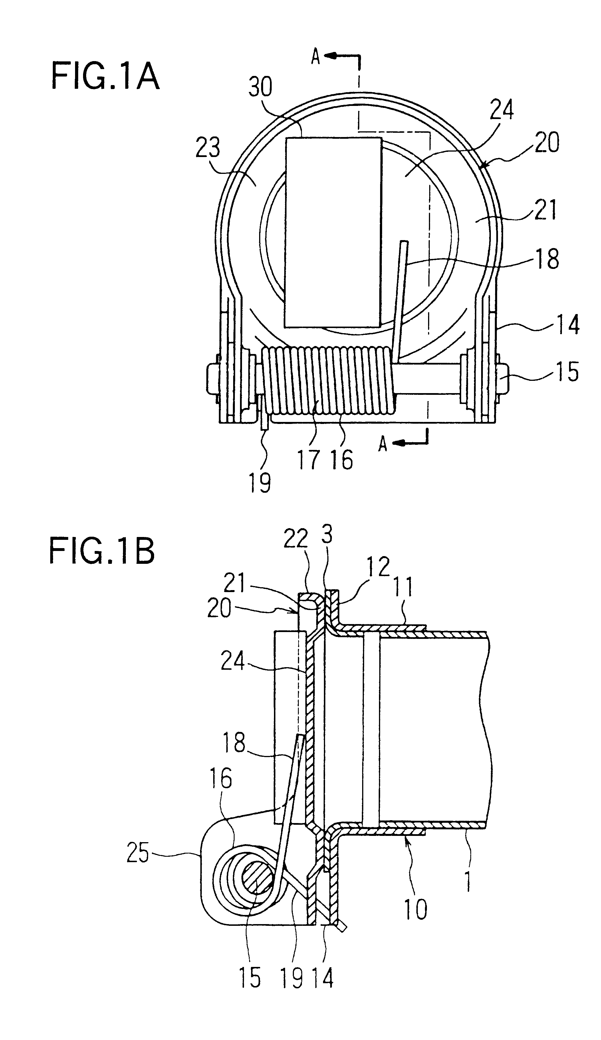
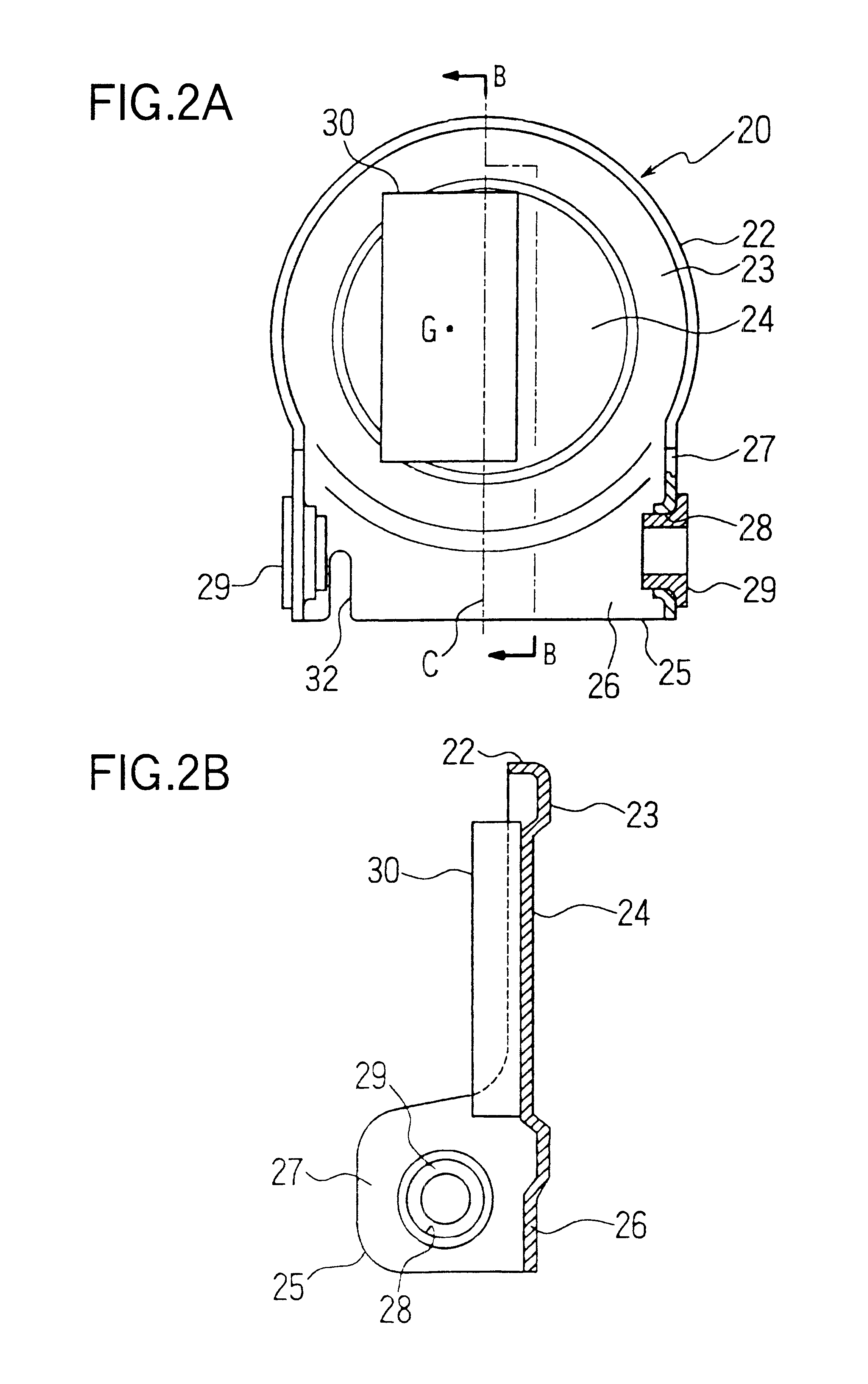
Each of FIGS. 1A and 1B shows a muffler pipe inside a muffler according to the first embodiment of the invention. FIG. 1A is a front view of the muffler pipe, and FIG. 1B is a cross-sectional view of the muffler pipe taken along the line A--A. Also, FIGS. 2A and 2B are enlarged views showing a valve disk in enlargement. FIG. 2A is a front view of the valve disk, and the FIG. 2B is a cross-sectional view of the valve disk taken along the line B--B.
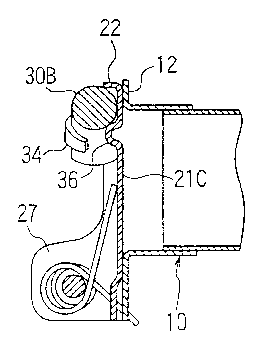
A support member 10 having a tubular portion 11 is joined to an end portion of the muffler pipe 1, with a flange 12 as a valve seat formed in a tube end of the support member 10.
A mesh sheet 3 made of stainless material is bonded to a flange 12 that is the valve seat or a contact surface of the support member 10 and extends to an inner wall of the tubular portion 11.
A part of the flange 12 is extended downward in the figure and bent like a U-shaped character in an opposite ...
second embodiment
The second embodiment of the present invention will be described below.
Each of FIGS. 3A and 3B shows a muffler pipe inside a muffler according to the second embodiment of the invention. FIG. 3A is a front view of the muffler pipe, and FIG. 3B is a cross-sectional view of the muffler pipe taken along the line A--A. Also, FIG. 4 is a side view of a valve disk.
A support member 10 having a tubular portion 11 is joined to an end portion of the muffler pipe 1, with a flange 12 as a valve seat formed in a tube end of the support member 10.
A part of the flange 12 is extended downward in the figure and bent like a U-shaped character in an opposite direction of the muffler pipe 1 to form a support bracket 14.
The support bracket 14 supports a hinge axis 15 as a rotation axis, and a valve disk 20 is borne on the hinge axis 15 rotatably.
The valve disk 20 has a valve wall 21 opposed to the flange 12 of the support member 10, and a flange 22 around the peripheral edge of the valve wall 21.
One end ...
third embodiment
A third embodiment of the invention will be described below. In the third embodiment, the weight is formed of a round bar steel.
FIGS. 7A to 7C are views showing the third embodiment of the invention. FIG. 7A is a front view, FIG. 7B is a cross-sectional view taken along the line B--B, and FIG. 7C is a side view of a valve disk.
A flange 22 is formed around the outer peripheral edge of an outer peripheral portion 23, and partially extended, as in the second embodiment. A hinge portion 25 like a U-shaped character is composed of a bearing portion 27 rising from a base portion 26 and its both ends to align with the support bracket 14 like a U-shaped character.
The flange 22 has a narrower width in a certain range of an arcuate portion R along the outer peripheral portion 23 that is most left away from a hinge axis 15, but has a broader portion 22a toward the hinge axis 15 to link to a bearing portion 27.
On a back face of a valve wall 21B, the weights 30 bent arcuately and made of round b...
PUM
 Abstract
Description
Claims
Application Information