Expandable delivery appliance particularly for delivering intravascular devices

a delivery appliance and expandable technology, applied in the field of expandable delivery appliances specifically for delivering intravascular devices, can solve the problems of affecting the delivery effect, and affecting the delivery effect, and achieving the effects of reducing the risk of implantation, and reducing the safety of patients

Inactive Publication Date: 2004-05-25
STRYKER EURO OPERATIONS HLDG LLC +1
View PDF13 Cites 131 Cited by
  • Summary
  • Abstract
  • Description
  • Claims
  • Application Information

AI Technical Summary

Benefits of technology

According to further features in the preferred embodiments of the invention described below, each of the supporting strips in the annular array is stiff in the longitudinal direction, but is formed with at least one integral hinge to permit its deformation in the lateral direction. More particularly, each of the supporting strips includes a strip of stiff material extending from the proximal end of the annular array to the distal end of the annular array and formed with at least one transversely-extending groove producing the at least one integral hinge. The transversely-extending groove is formed on one surface of the strip of stiff material to permit the strip to be laterally deformed more easily in the direction of that surface than in the opposite direction.
It will thus be seen that such a delivery appliance eliminates the need for an inflatable balloon, and therefore avoids many of the problems and difficulties, as described above, associated with such inflatable balloons. This make the delivery appliance particularly useful in medical applications for delivering intraluminal devices, especially intravascular devices.

Problems solved by technology

This can be extremely hazardous or even fatal.
In some situations, for example in the deployment of self-expandable intraluminal devices in the aortic arch or in the intracranial arteries, the complete blockage of the lumen by the balloon during the implantation process, even for a short period of time, may also be highly hazardous or even fatal.
Another drawback in the use of a conventional balloon catheter for self-expanding intervascular devices is the danger of over inflation, which can cause significant damage to the intimal and the medial layers of the vessel wall, and increased restenosis of the intervascular devices.
The use of a conventional balloon catheter in a large diameter vessel, such as the aorta, may also be problematical because of the difficulty of expanding the balloon to the large size required for this application with sufficient force to anchor the intravascular device in place without damaging the vessel walls.

Method used


Image

  • Expandable delivery appliance particularly for delivering intravascular devices
  • Expandable delivery appliance particularly for delivering intravascular devices
  • Expandable delivery appliance particularly for delivering intravascular devices

Examples


Embodiment Construction

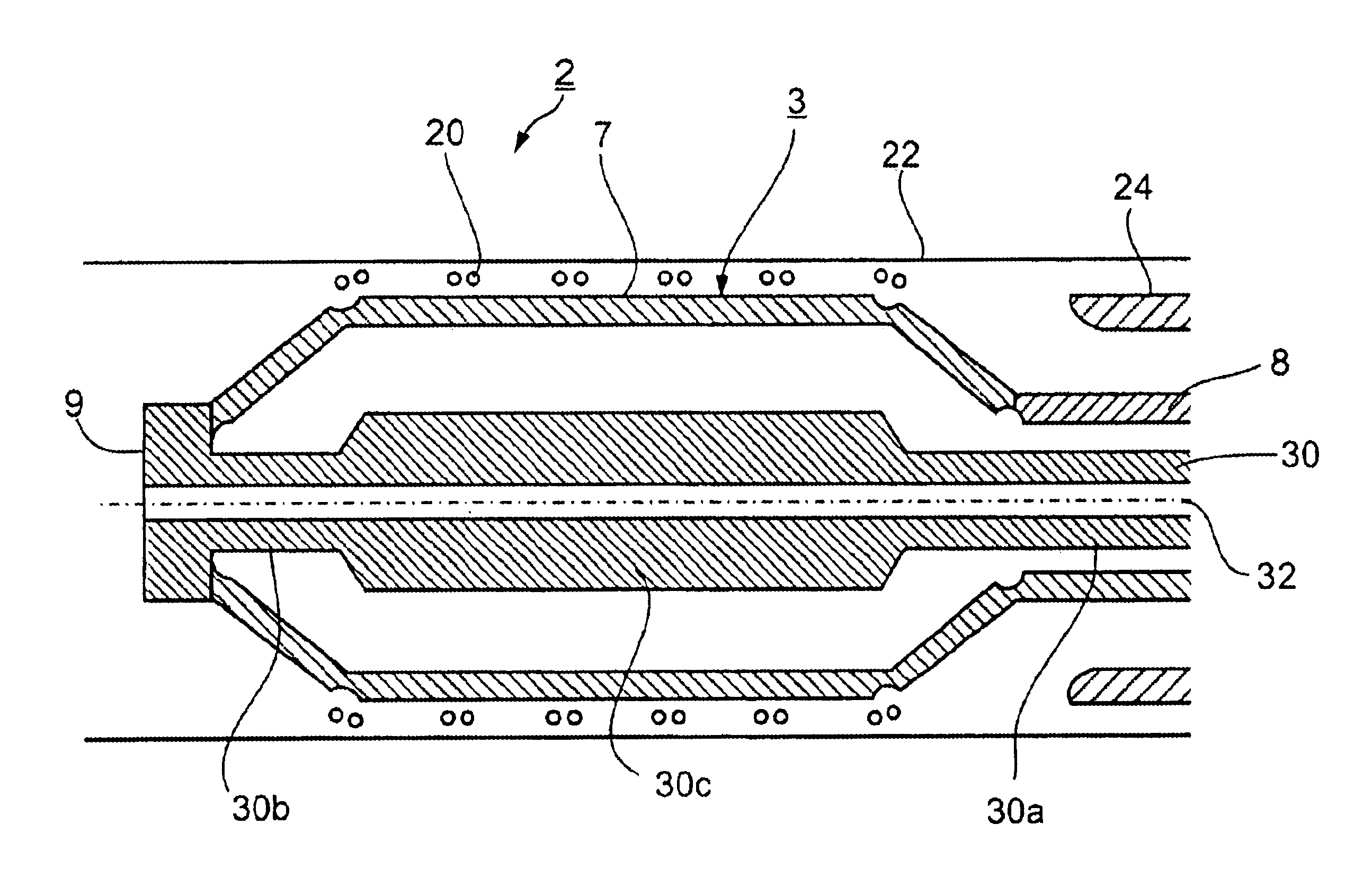
The delivery appliances illustrated in the drawings as preferred embodiments of the invention do not utilize expansion balloons, and therefore avoid many of the difficulties briefly described above in the use of such balloons, for delivering intraluminal devices, particularly intravascular devices, into a lumen of a subject's body. The delivery method is substantially the same as in traditional methods, except that the expansion and contraction of the delivery appliance is produced by effecting relative movement between mechanical elements, rather than by the expansion and contraction of a balloon. Accordingly, the description below will concern only the delivery appliance itself and the manner in which it is expanded and contracted when deploying the intravascular device, as the remainder of the deployment procedure would be substantially the same as when using the traditional expansion balloon.

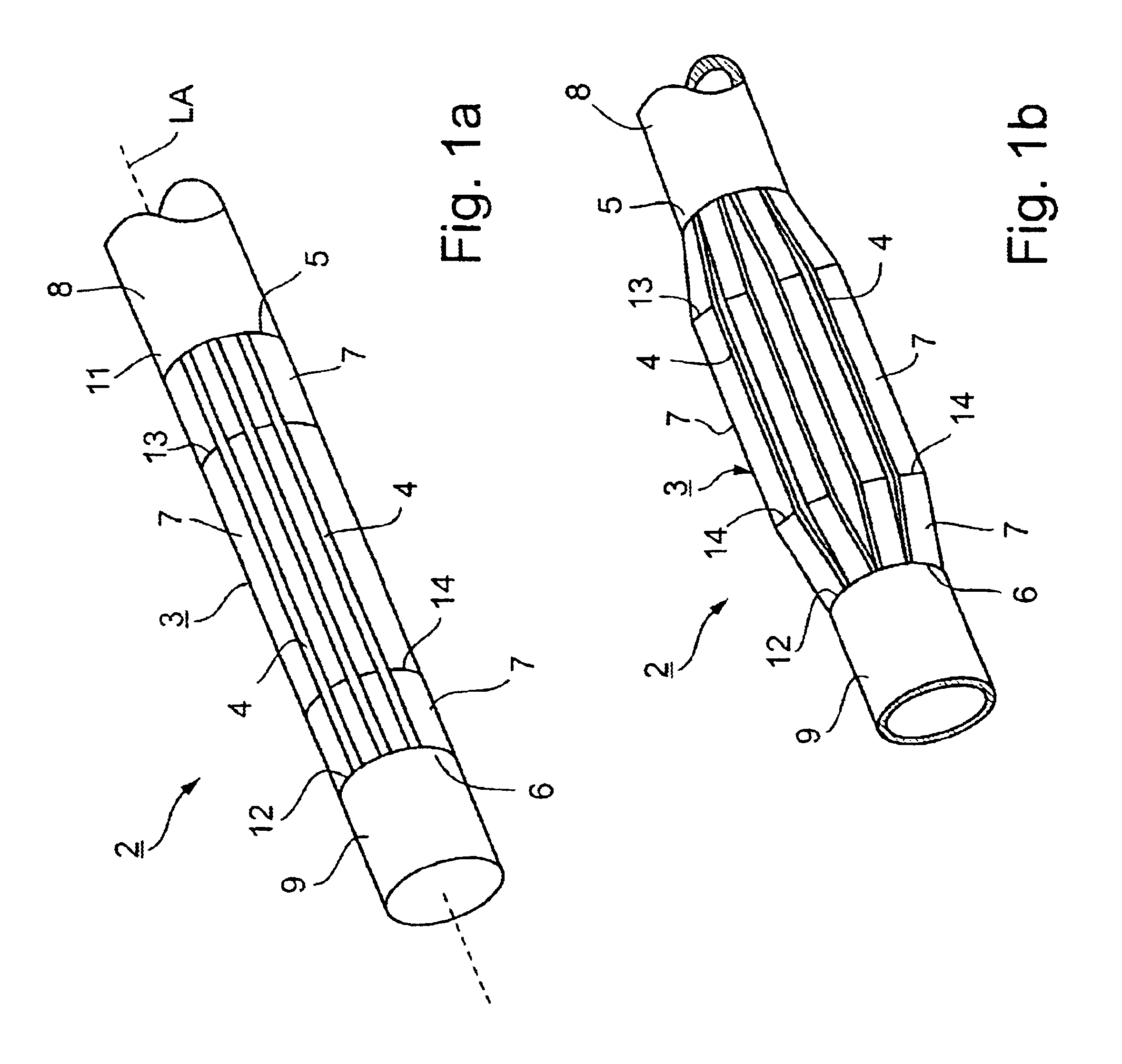
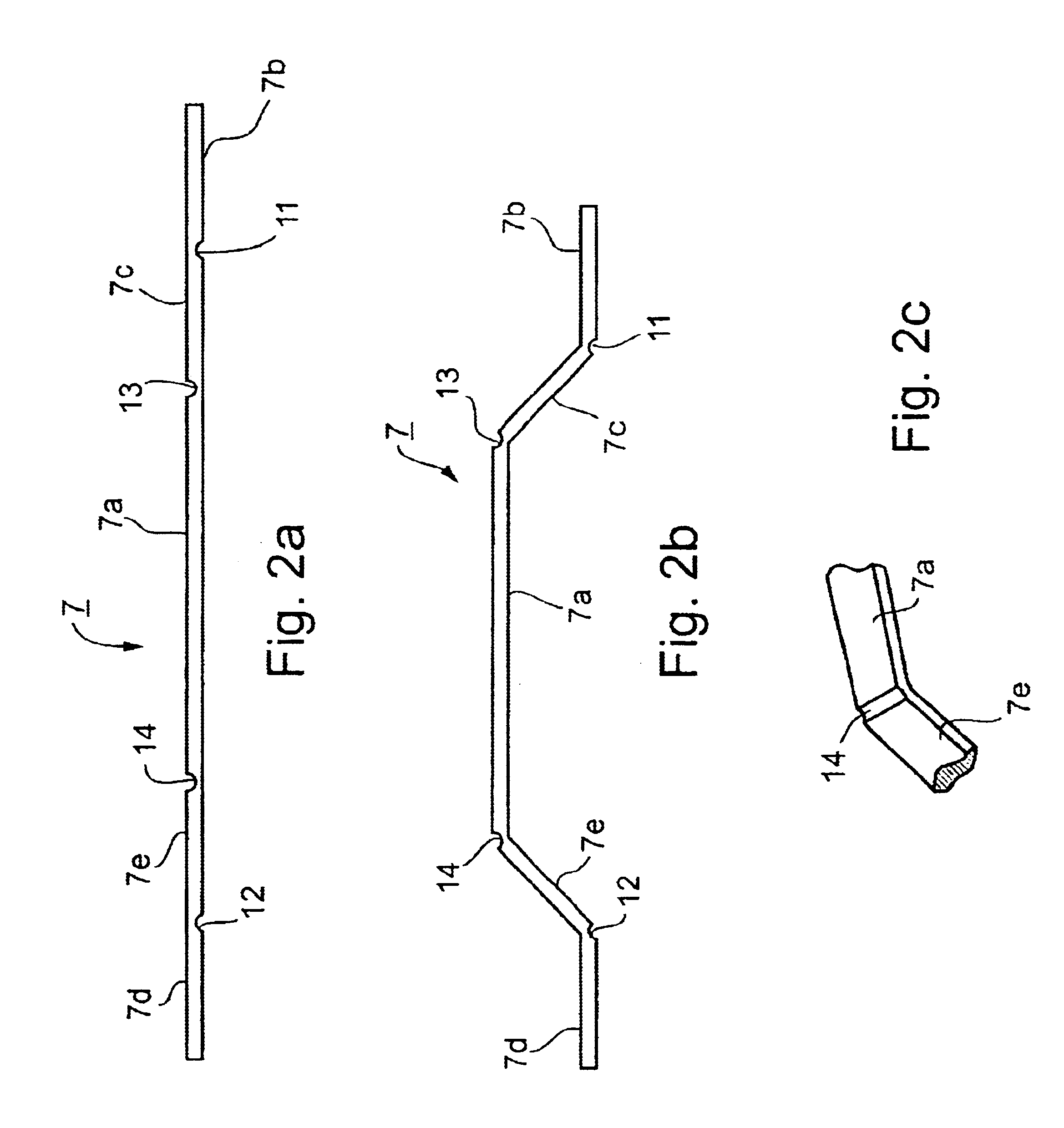
The Embodiment of FIGS. 1a-3c

FIG. 1a illustrates the external appearance of the expandab...


PUM


Abstract

A delivery appliance for delivering an expandable annular device, particularly an expandable intravascular device, to a desired location in a lumen, includes an annular array of supporting strips extending from a proximal end of the annular array to a distal end of the annular array, to define an annular supporting surface for the expandable annular device. Each of the supporting strips is laterally deformable to radially expand or radially contract the annular array and the annular supporting surface defined thereby. A connecting stem passes through the annular array of supporting strips and has a distal end coupled to the supporting strips at the distal end of the annular array for axial movement therewith, and a proximal end passing through the proximal end of the annular array of supporting strips for axial movement with respect thereto. The proximal end of the connecting stem is axially movable in opposite directions to move the distal end of the annular array axially away from or towards, the proximal end of the annular array to radially contract or radially expand the annular supporting surface.

Description

FIELD AND BACKGROUND OF THE INVENTIONThe present invention relates to delivery appliances for delivering an expandable annular device to a desired location in a lumen. The invention is particularly useful in medical applications, for delivering an expandable intraluminal device, especially an intravascular device, to a desired location in the lumen of a subject's body, and is therefore described below with respect to such an application.Numerous types of implantable intravascular devices, such as stents, grafts, sensors, and filters are well known in the prior art. Also well known are delivery systems and methods for guiding these devices to the proper location within the body and for deploying them at the desired location, as described, for example, in U.S. Pat. Nos. 6,221,043; 4,950,227; 5,634,928; 5,108,416; and 5,549,613. Such delivery systems typically include balloon-type catheters, in which the balloon is deflated to receive the intravascular device and to deliver it to the d...

Claims


Application Information

Patent Timeline
Patent Type & Authority Patents(United States)
IPC IPC(8): A61F2/06A61F2/84
CPCA61F2/958
Inventor YODFAT, OFERRAPAPORT, AVI
Owner STRYKER EURO OPERATIONS HLDG LLC
Why Eureka
Try Eureka