Photodetector, photosensing position detector, coordinate input device, coordinate input/output apparatus, and photodetection method

a technology of photodetector and detector, which is applied in the direction of counting objects on conveyors, static indicating devices, instruments, etc., can solve the problems of narrow dynamic range of devices, virtually unavailable tracking means for tracking variations in an amount of light, and inability to detect the effect of light intensity

Inactive Publication Date: 2004-05-25
CANON KK
View PDF3 Cites 48 Cited by
  • Summary
  • Abstract
  • Description
  • Claims
  • Application Information

AI Technical Summary

Problems solved by technology

Tracking means for tracking variations in an amount of light is virtually unavailable.
This means that the dynamic range of the device is narrow.
Since means for detecting a received signal as coordinate information is used, tracking means for tracking variations in an amount of light is virtually unavailable.
When the signal level is low (when the level of the light beam is low), the above timing is slow, and additional storage of charge is performed for a long period of time.

Method used


Image

  • Photodetector, photosensing position detector, coordinate input device, coordinate input/output apparatus, and photodetection method
  • Photodetector, photosensing position detector, coordinate input device, coordinate input/output apparatus, and photodetection method
  • Photodetector, photosensing position detector, coordinate input device, coordinate input/output apparatus, and photodetection method

Examples


first embodiment

As already discussed, the present invention is directed to a method for expanding dynamic range to the strength of incident light. A first example of the method for expanding dynamic range will now be discussed.

A timing sequence in the first example is shown in FIG. 18 and FIG. 19.

In the first example of the first embodiment, the external control of the ring CCD and the synchronization between the ring CCD and the LED blinking remain largely the same as those in the known devices. The difference is that a storage quantity per blinking cycle is reduced by deviating the signal "IRCLK" of the electronic shutter from the signal "LED_IR" (or "IR") in phase by a predetermined amount at the beginning of one coordinate sampling, and that the signal "IRCLK" and the signal "LED IR" (or "IR") are aligned in phase immediately prior to the end of the one coordinate sampling by slightly deviating the signal "IRCLK" from the signal "LED_IR" (or "IR") in frequency.

Specifically, the timing sequence ...

second embodiment

FIG. 25 is a perspective view showing a coordinate input device in accordance with a second embodiment of the present invention. FIG. 26 is a block diagram of the coordinate input device.

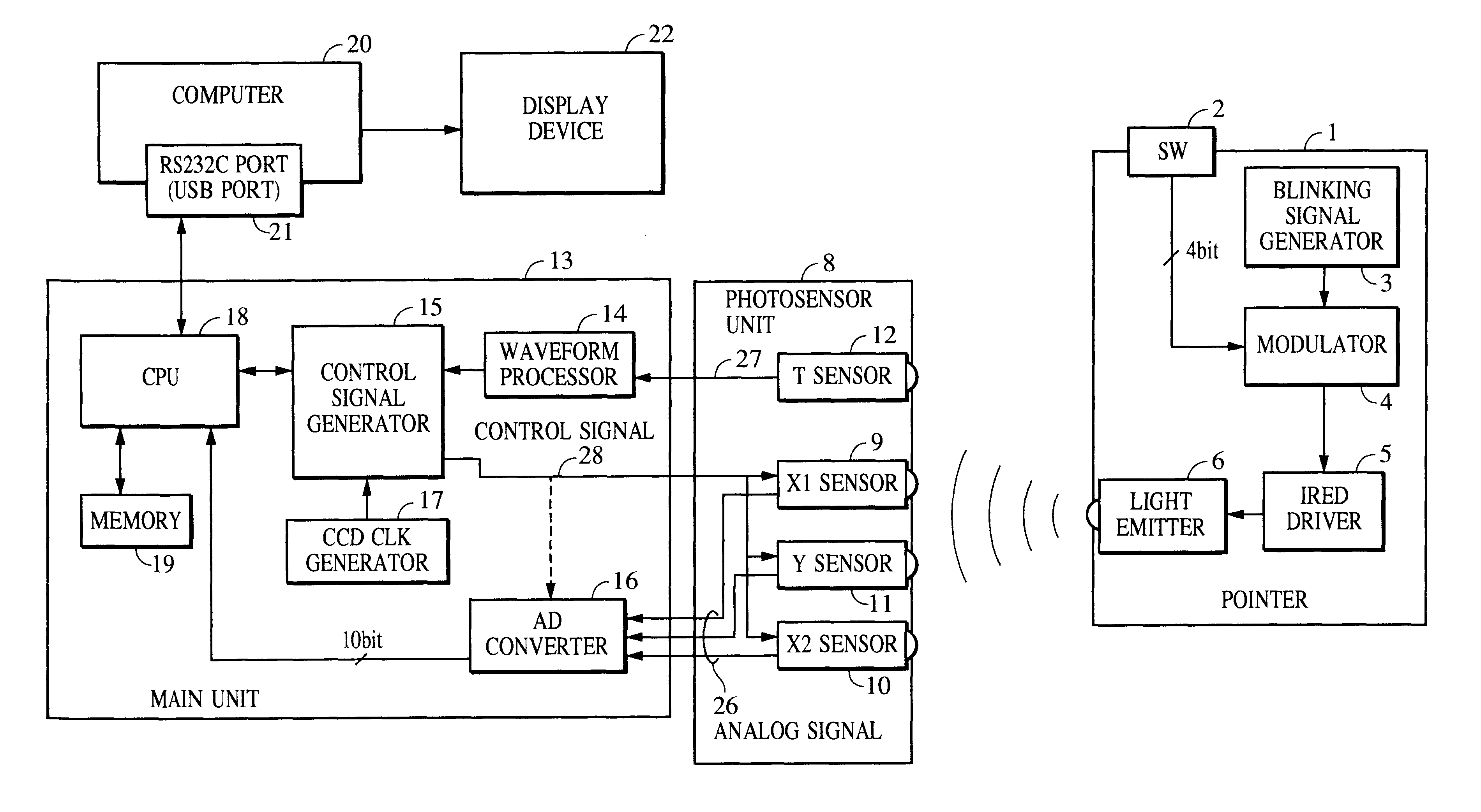
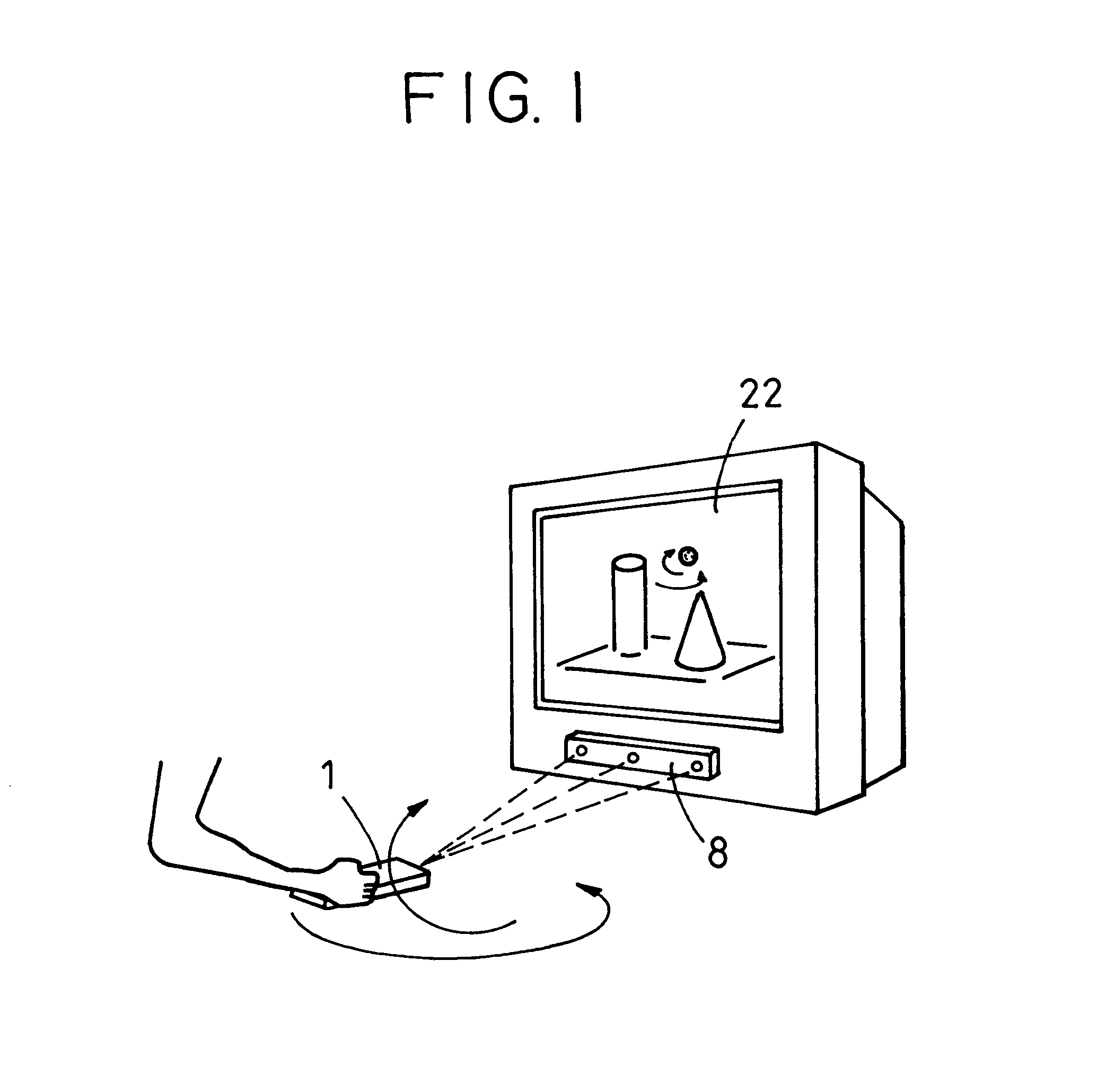
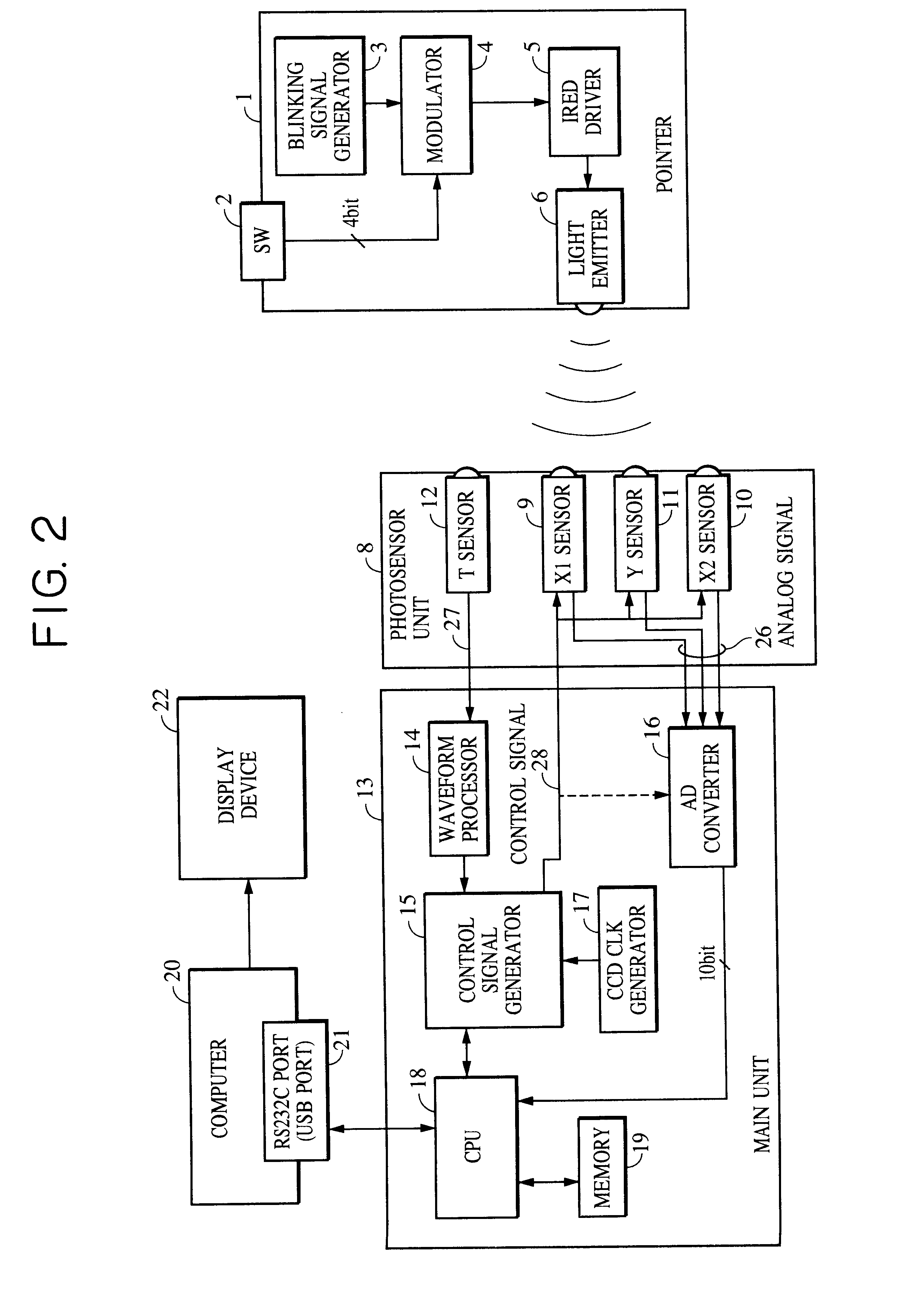
The coordinate input device includes a pointer 101 which forms a light spot 103 on a screen 102 serving as a coordinate input surface, a photosensor unit 127 which detects position coordinates of the light spot 103 generated on the screen 102, and a signal processor 124 which controls the photosensor unit 127 and calculates coordinate information from a signal into which the light spot 103 is photoelectrically converted by the photosensor unit 127.

FIG. 27 shows a projection-type display apparatus 109 which presents an image on the screen 102 while echoing back coordinate position information (of a cursor and a path, for example) indicated by the pointer 101.

The pointer 101 includes a light emitter element 115 such as a semiconductor laser or an LED for directing an optical beam, a blinking signal ge...


PUM


Abstract

A photodetector includes a photoreceiving unit which receives a light beam that blinks a plurality of times per detection period and converts the received light beam into an output signal. A signal processing and control unit controls the photoreceiving unit so that the output signal increases in strength as a blinking cycle count increases in each detection period.

Description

1. Field of the InventionThe present invention relates to a photodetector, a photosensing position detector, a coordinate input device, a coordinate input / output device, and a photodetection method.2. Description of the Related ArtSome known coordinate input devices input two-dimensional coordinates on a screen of a large-scale display device by using a pointer, thereby entering drawings, characters or commands for controlling a system to an externally connected CPU (Central Processing Unit). Another known coordinate input device inputs three-dimensional coordinates by manipulating a pointer in a three-dimensional space, thereby entering a path of three-dimensional motion, information of the presence of an object, or commands for controlling a system.Specifically, a coordinate input device for a large-scale display picks up a light spot on a screen using a CCD area sensor or a CCD linear sensor, and determines the position of the focused light spot on the sensor screen in response t...

Claims


Application Information

Patent Timeline
Patent Type & Authority Patents(United States)
IPC IPC(8): G09G5/00H01L31/00G06F3/033G06F3/042
CPCG06F3/0308G06F3/0325
Inventor KOBAYASHI, KIWAMU
Owner CANON KK
Why Eureka
Try Eureka