Optical fiber clamping apparatus to hold fiber cable while providing retractable distance across module unit

a technology of optical fiber and clamping apparatus, which is applied in the direction of optics, fibre mechanical structures, instruments, etc., can solve the problems of reducing the clamping force of the inner fiber cable and the outer fiber jacket tubing, reducing and affecting the performance of the fiber. , to achieve the effect of improving the clamping force of the fiber cable and reducing insertion and return losses

Inactive Publication Date: 2004-05-25
II VI DELAWARE INC
View PDF4 Cites 113 Cited by
  • Summary
  • Abstract
  • Description
  • Claims
  • Application Information

AI Technical Summary

Benefits of technology

The present invention discloses a fiber routing tray with an internal spool to hold excess fiber cable length, a fiber clamping slot to seat fiber cables for clamping, a retention bar with contoured fiber clamps to provide uniform and sufficient clamping force to a fiber cable for strain relief, a precision dimensio...

Problems solved by technology

Principle shortcomings of the flat shaped clamp include uneven clamping force of the fiber cables and excessive localized clamping pressure on the topside of the buffered fiber cable, which alters the fiber performance.
The flat clamp creates non-uniform clamping pressure around a fiber cable especially on the topside, which results in insertion losses and return losses.
Other prior art used ep...

Method used


Image

  • Optical fiber clamping apparatus to hold fiber cable while providing retractable distance across module unit
  • Optical fiber clamping apparatus to hold fiber cable while providing retractable distance across module unit
  • Optical fiber clamping apparatus to hold fiber cable while providing retractable distance across module unit

Examples


Embodiment Construction

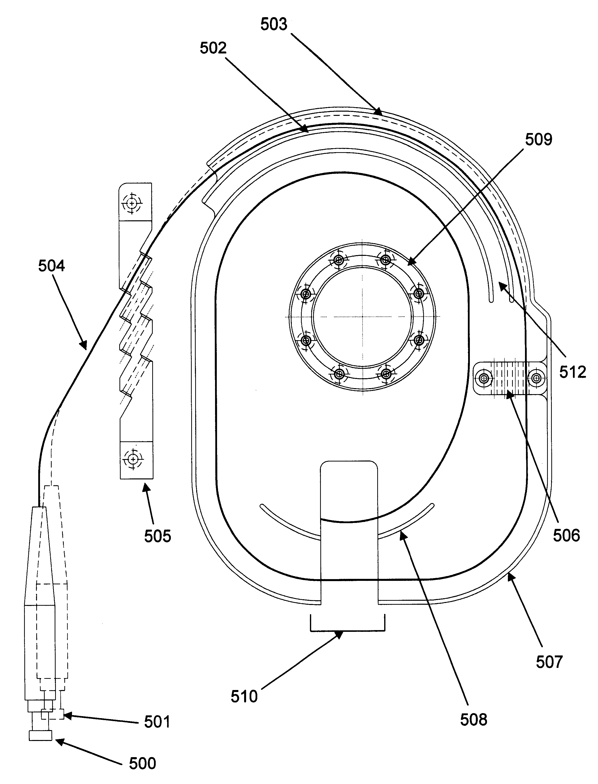
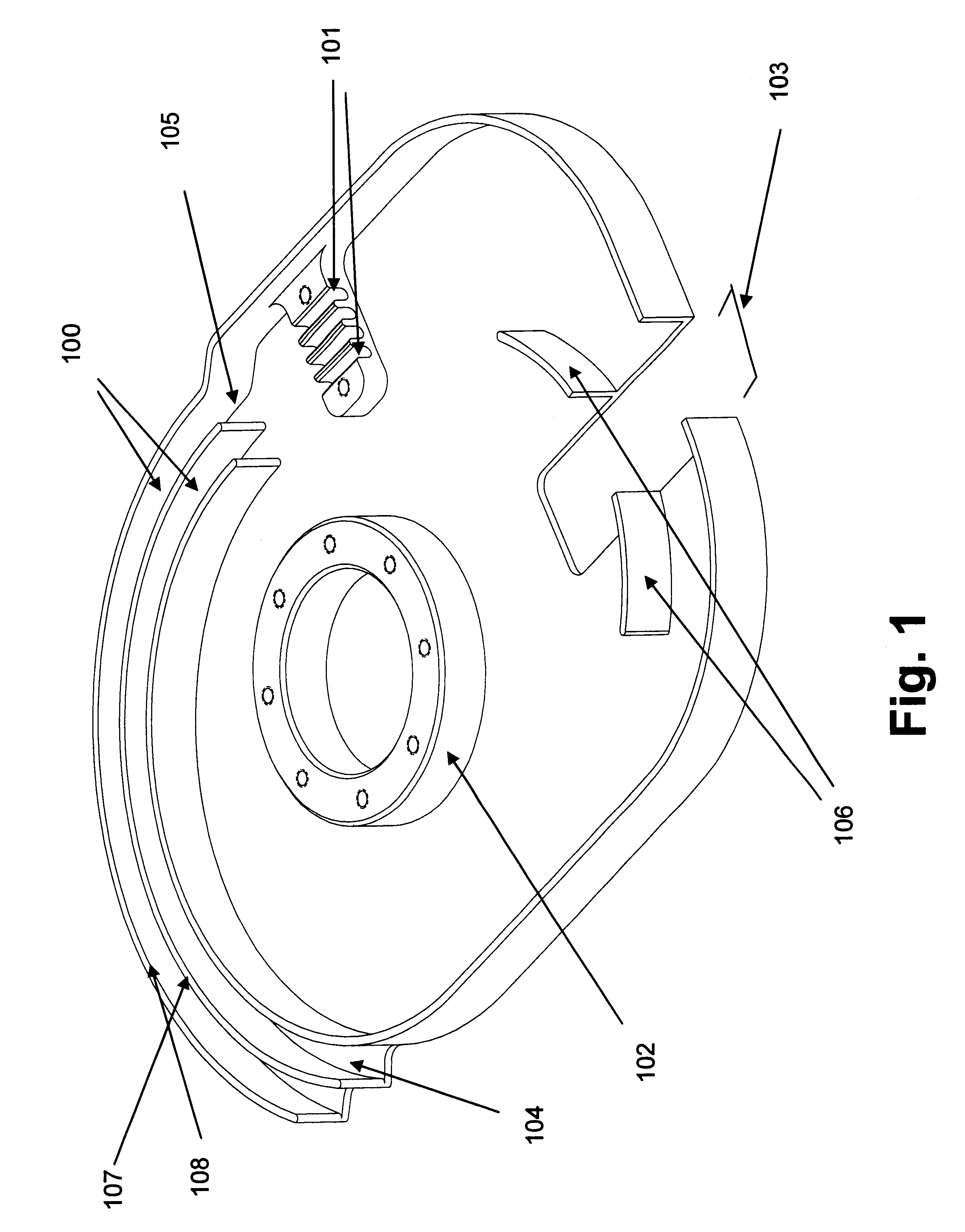
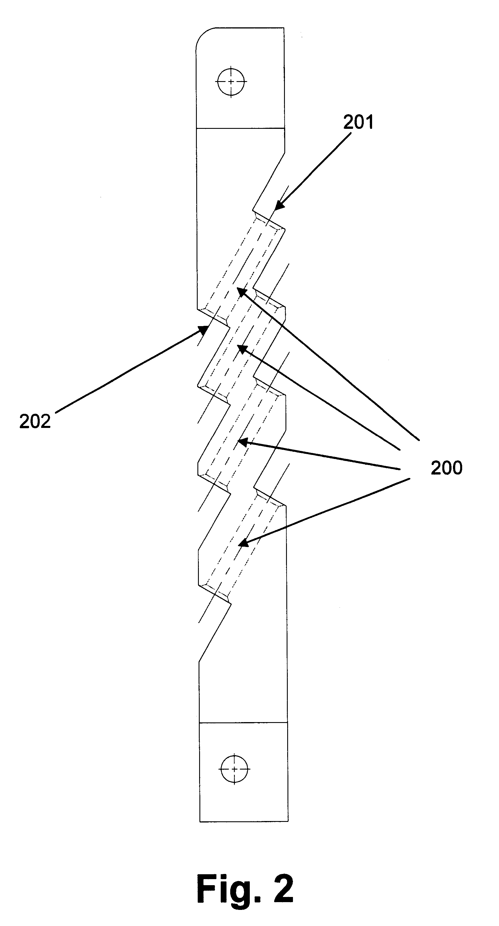
FIG. 1 is an illustration of a fiber reel routing tray depicting the location of fiber channel slots 100, fiber cable clamping slots 101, fiber cable spool 102, fiber routing fence 106, and fiber exit opening 103. During assembly, an external fiber cable passes through the fiber entry block passages 200 and follows the curved fiber channel routing slots 100 onto the fiber cable clamping slots 101 where the fiber cables are clamped and held into place with a contour retention clamp 300. The fiber cables then proceed around the outside fiber routing fence 106, which prevent the fiber cables from overbending and tangling inside the fiber tray. The fiber cable spool 102, which have mounting holes for attaching the fiber routing tray on to a PCB, also functions to route fiber cables. The fiber cables may be wrapped around the fiber cable spool 102 and fiber routing fence one or more times, and then eventually make its way onto the fiber tray opening 103 and onto other optical modules and...


PUM


Abstract

A fiber routing tray to hold, organize, and route fiber cables from external sources to other optical modules and optical components. The fiber routing tray mechanical device comprises a fiber entry block, fiber channel slot, retention bar with fiber clamps, fiber clamping slots, curved fiber routing fence, and a fiber exit opening. A retention bar with a contoured fiber retention clamps is used to hold fiber cables in place, provide a strain relief to a fiber cable, and distribute uniform clamping force on the fiber cable preventing insertion and return losses. Curved fiber channel slots with a preferable width help route fiber cables and prevent them from overbending. In addition, these fiber channel slots control the extension and retraction distance of the fiber cables during external fiber cable assembly. A curved fiber routing fence help route fiber cables and help prevent them from over-bending and tangling inside of the fiber reel tray. An exit opening allows fiber cables to drop below the fiber tray before the fiber cables are attached to the optical devices and optical modules.

Description

The present invention relates generally to the field of optical devices, and particularly a fiber routing tray mounted on a PCB.BACKGROUND OF INVENTIONIn telecommunications equipment, optical modules and electronic circuits for signal monitoring, signal processing, temperature control, and motion control are typically assembled on a Printed Circuit Board (PCB) module which is then inserted into a modular network system. Depending on the requirement, specific fore-mentioned components are selected and assembled on a PCB for a particular application. A fiber routing tray mounted on a same PCB is utilized to help route incoming fiber cables to each of the optical modules, optical devices, and electronic circuitry on the PCB. The assembled PCB, also known as a daughter board, is inserted into a motherboard used in a telecommunication equipment.The purpose of a fiber routing tray is to hold excess fiber cable length, provide a strain relief, and guide fiber cables onto other optical modu...

Claims


Application Information

Patent Timeline
IPC IPC(8): G02B6/44
CPCG02B6/4471G02B6/4453
Inventor GUAN, WILLIAM Z.
Owner II VI DELAWARE INC
Why Eureka
Try Eureka