Axial flow catalyst pack

a catalyst pack and axial flow technology, applied in the direction of physical/chemical process catalysts, metal/metal-oxide/metal-hydroxide catalysts, etc., can solve the problems of recirculation of decomposed flow, material wear, and relatively fragile materials, etc., to achieve efficient catalyst contact and promote uniform mixing

Inactive Publication Date: 2004-06-08
AEROJET ROCKETDYNE INC
View PDF4 Cites 59 Cited by
  • Summary
  • Abstract
  • Description
  • Claims
  • Application Information

AI Technical Summary

Benefits of technology

It is another object of the present invention to provide a catalyst bed having a generally cylindrical configuratio

Problems solved by technology

These materials are subject to wear and are relatively fragile (the alumina granules), and do not possess a consistent flow resistance (stacked screens).
The uneven flow resistance leads to localized flow restrictions which result in recirculation of the decomposed flow, unpredictable start/stop behavior and unpred

Method used


Image

  • Axial flow catalyst pack
  • Axial flow catalyst pack
  • Axial flow catalyst pack

Examples


Embodiment Construction

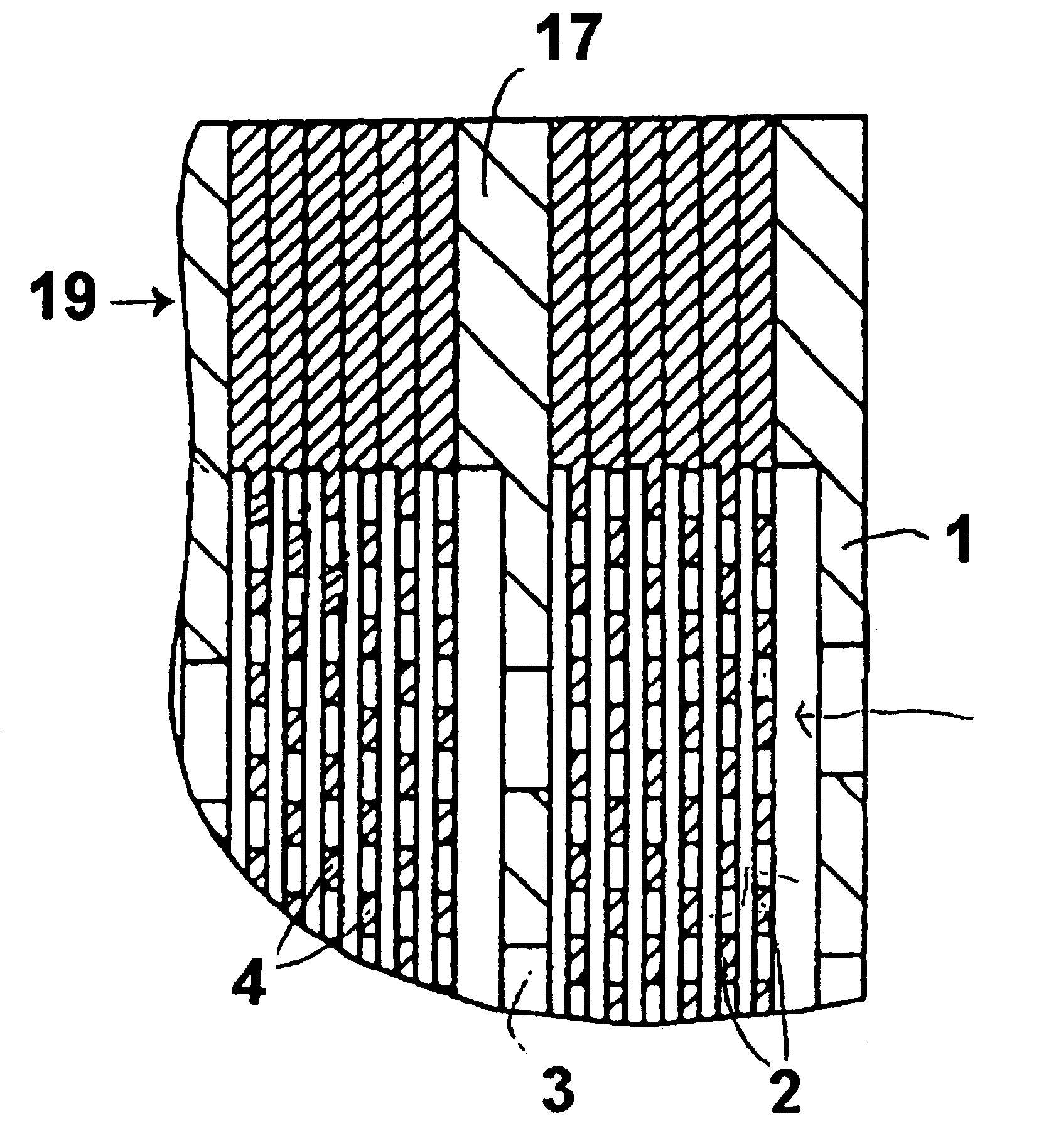
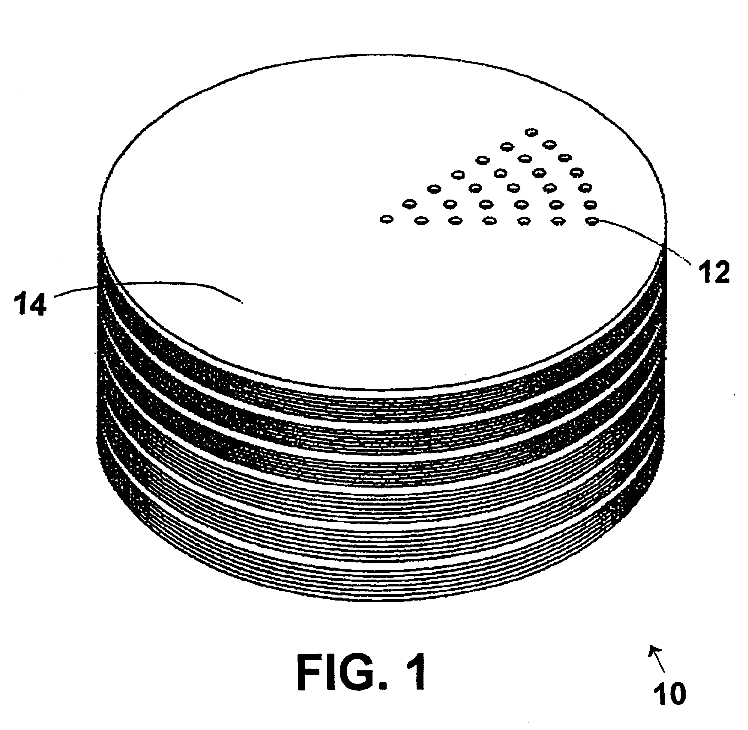
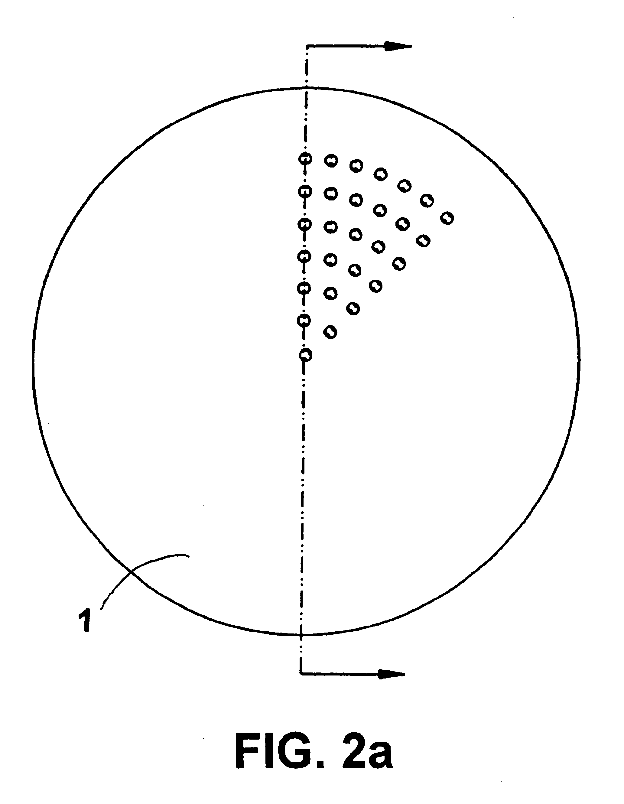
The axial flow platelet fabricated catalyst bed 10 shown in FIG. 1 uses precise thru-etched openings 12 in each platelet 14 so that the flow can "diffuse" from the inlet platelet to each succeeding platelet. Passage cross sectional areas can be tailored by increasing the proportion of the platelet that is open and thereby the passage cross sectional and surface area can increase as the flow gasifies. This is illustrated in FIG. 2 which shows the flow path of the monopropellant through the inventive catalyst bed. The flow passes through a metering plate 1 to distribute the monopropellant uniformly across the catalyst bed and then passes through a secession of "surface enhancement" plates 2 that have a large catalytic surface area and the desired open area ratio. Then the flow passes through another metering platelet 3 and "surface enhancement" platelet group 4. Each succeeding metering platelet's fraction of open area will be greater than the previous metering platelet and less than ...


PUM

PropertyMeasurementUnit
Flow rateaaaaaaaaaa
Sizeaaaaaaaaaa
Ratioaaaaaaaaaa

Abstract

A stack of very thin metal plates provides high surface area for catalytic decomposition of a fluid flowing axially from upstream to downstream through the stack. Each plate has flow-through passages of selected size and location to promote uniform flow and good surface contact with a catalyst surface on the plates. The downstream surface of each plate is etched to provide gaps between plates for lateral fluid flow. The plates are divided into groups separated by metering plates that promote more uniform flow from group to group.

Description

The present invention relates generally to apparatus for catalytic decomposition of monopropellant fuels and more specifically to a plurality of stacked thin metal plates having precise flow passages to provide selected uniform flow characteristics across each plate while promoting thorough catalytic surface contact with well mixed monopropellant.PRIOR ARTCatalytic decomposition of monopropellant fuels, i.e., H2O2 and N2H4, requires the use of a transitional metal catalyst to initiate and sustain decomposition. Catalyst beds are designed to supply large surface areas of catalytic substance and thorough mixing of the monopropellant to facilitate complete decomposition. A peroxide catalyst bed typically uses silver screen packs, while a N2H4 system typically consists of iridium deposited on alumina granules. Extruded ceramic cores have also been employed.In all instances the catalyst was applied to an aggregate material. These materials are subject to wear and are relatively fragile (...

Claims


Application Information

Patent Timeline
IPC IPC(8): B01J19/24B01J23/89B01J23/755B01J35/04B01J35/00C01B3/04C01B3/00C06D5/00C01B13/02C06D5/04
CPCB01J19/2485B01J19/249B01J23/755B01J23/892B01J35/04C01B3/04C01B13/0214C06D5/04B01J2219/00164B01J2219/2453B01J2219/246B01J2219/2479B01J2219/2482B01J2219/2485Y02E60/364Y02E60/36
Inventor PONZO, JAMES B.SCHINDLER, ROBERT C.MUEGGENBURG, HANS HARRY
Owner AEROJET ROCKETDYNE INC
Why Eureka
Try Eureka