Dual stiffness bearing damping system

a damping system and bearing technology, applied in the direction of elastic bearings, bearings, rigid support of bearing units, etc., can solve the problems of affecting the lift, and reducing the lift effect of dampers

Inactive Publication Date: 2004-06-08
BEACON POWER LLC
View PDF9 Cites 32 Cited by
  • Summary
  • Abstract
  • Description
  • Claims
  • Application Information

AI Technical Summary

Problems solved by technology

Loss of vacuum in an energy storage system, however, would produce higher temperatures due to additional frictional energy losses, which manifest as heat losses.
If such an unevacuated energy storage system were equipped to monitor temperatures, which is common, the energy storage system likely would be shutting down constantly.
For example, it is undesirable for a damper to affect the lift system of a rotor that is supported by magnetic bearings.
In another example, low radial stiffness reduces the dynamic force acting on the bearing, which can extend the bearing's service life.
In yet another example, stiffer dampers produce stiffer flywheel assemblies, which are more susceptible to problems associated with imbalances.
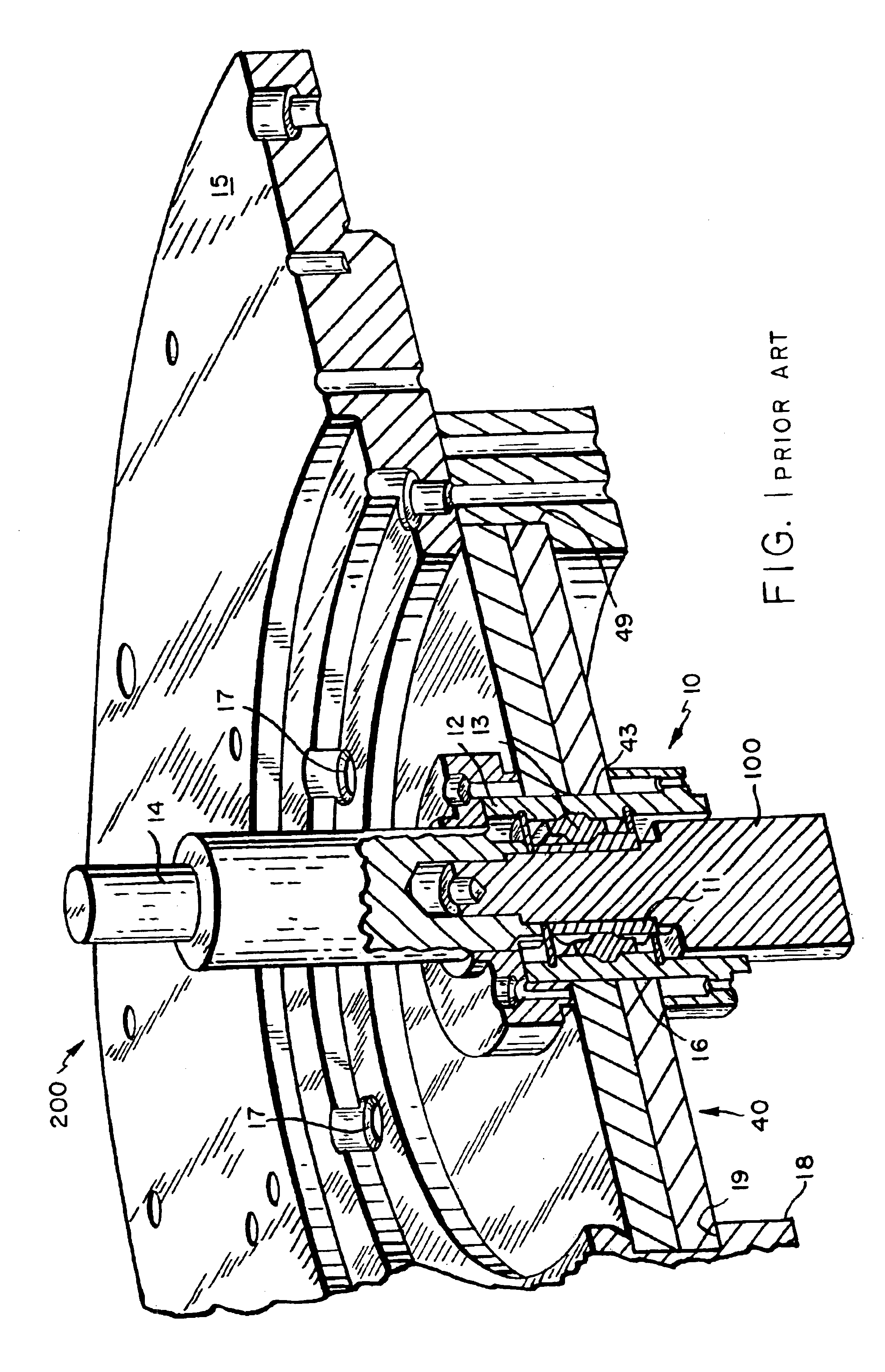
One problem with flexible dampers, however, is that, in contrast with more rigid dampers, flexible dampers permit relatively large deflections, displacements, and / or movements, which, under normal, i.e., design, operating conditions, is acceptable.
However, under abnormal or a typically operating conditions, e.g., during a period of extreme external loads and / or vibrations such as from an earthquake or other large dynamic force, flexible dampers of the prior art are unsuitable.
Indeed, excessive deflection during periods of extreme external vibrations can cause flywheel assembly moving parts to contact stationary parts with potentially catastrophic consequences.
(ii) local overheating, which can destroy the material properties of the rotor, stator and / or other component parts of the energy storage system;
(iii) damage to the rotor further causing a misbalance, which makes the rotor dynamically unstable; and / or
(iv) damage to the rotor increasing the clearance between the rotor and stator assemblies, which additional clearance could exceed the capability of the drag pump to effectively evacuate the energy storage system, causing a loss of vacuum.
This produces a dilemma.
Moreover, the flywheel assembly likely would be larger.

Method used


Image

  • Dual stiffness bearing damping system
  • Dual stiffness bearing damping system
  • Dual stiffness bearing damping system

Examples


Embodiment Construction

As previously stated, flywheel-based, evacuated energy storage devices ("flywheel assemblies") are relatively simple devices for readily storing and recovering energy. Conceptually, the rotor of the flywheel is rotated and mechanical kinetic energy is stored, e.g., primarily in the outermost portion, or rim, of the flywheel assembly. The amount of energy stored in the rim of a flywheel assembly is directly proportional to its mass and to the square of the rotational velocity of the flywheel. Consequently, to those skilled in the art, it is practical to develop flywheels that rotate at ever-increasing velocities.

Because state-of-the-art flywheel assemblies are designed to operate at increasingly higher velocities, designers must be concerned with transitioning the flywheel assembly through its critical velocity during power up. Indeed, during this transition, the flywheel assembly is subjected to deleterious resonance as the operating speed transitions to and then past the critical v...


PUM


Abstract

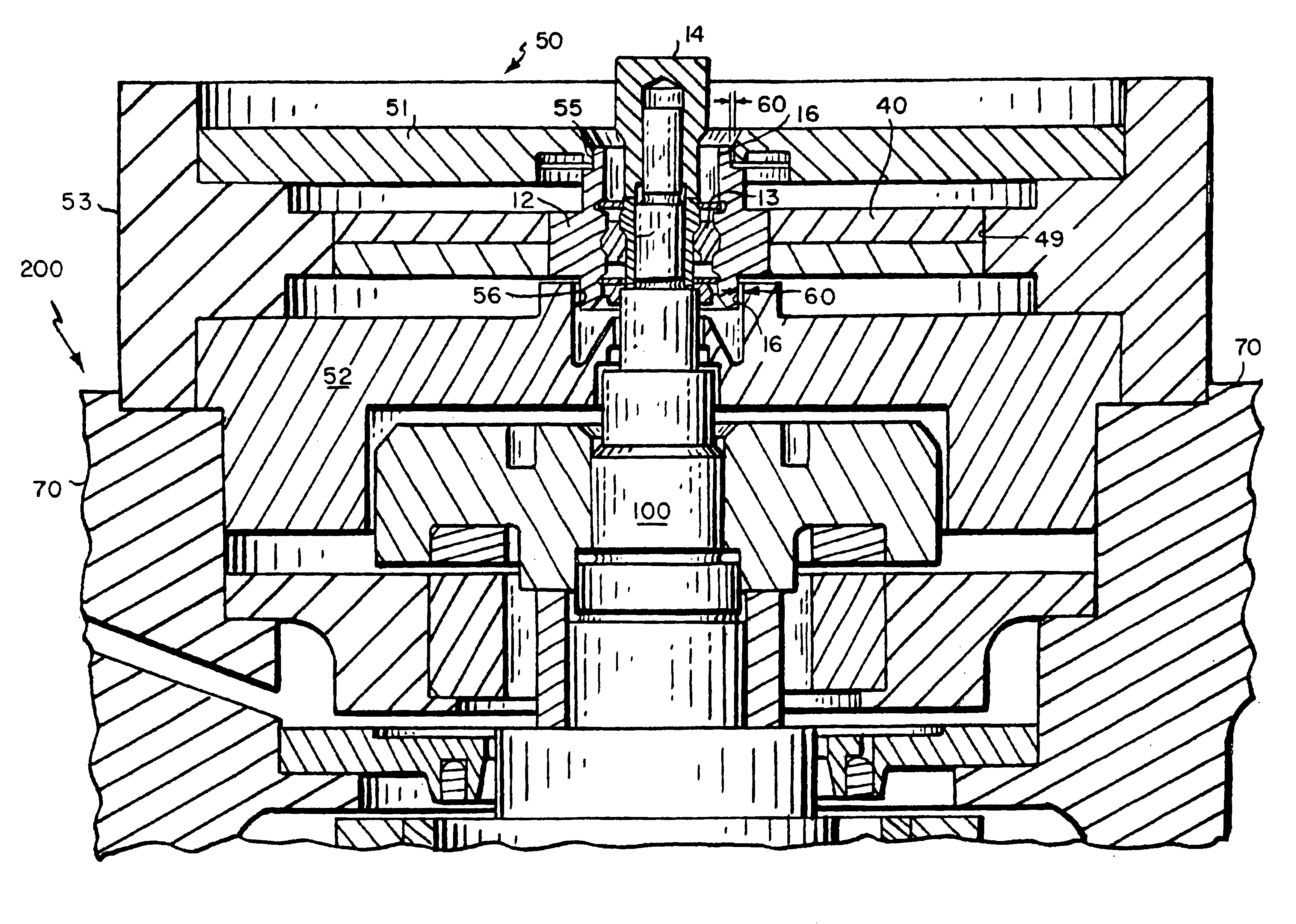
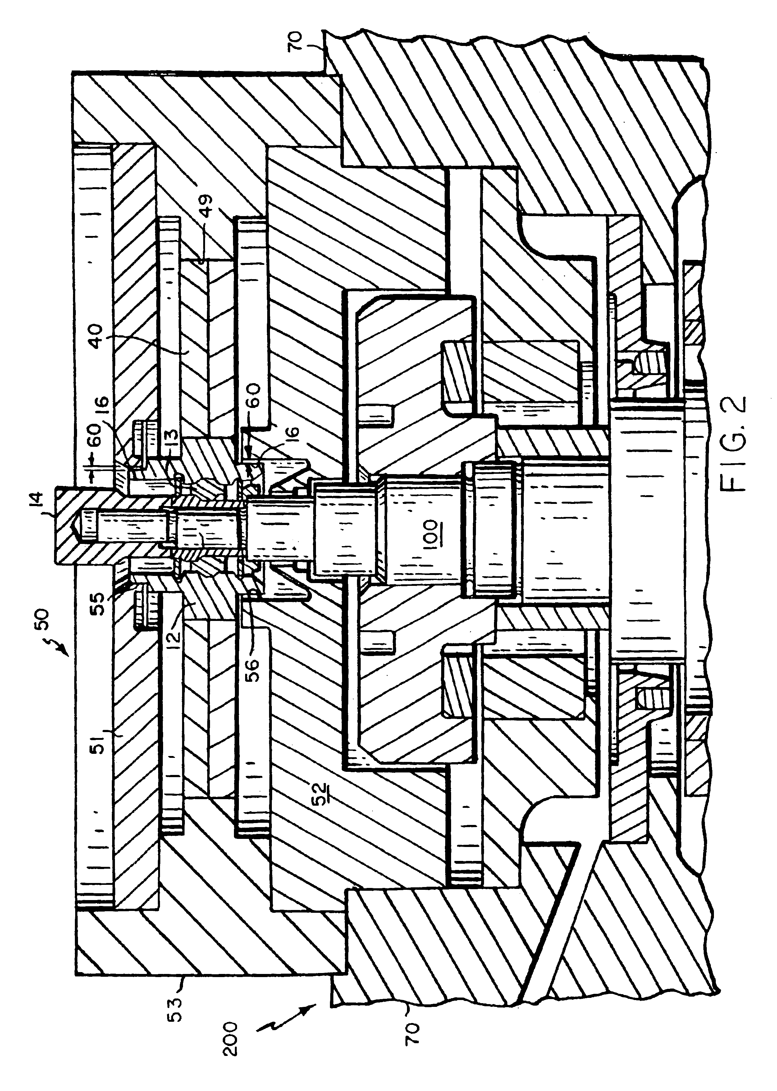
In one aspect of the present invention discloses a dual-stiffness damping system for an evacuated energy storage system, the damping system comprising one or more flexible dampers and a plurality of more rigid bumpers, and a method of damping an evacuated energy storage system using dual-stiffness damping. Indeed, under normal operating conditions, a flexible damper, having a stiffness of about 500 lb / in to about 4000 lb / in, minimizes the rigid body critical speed of the rotor assembly of the energy storage system, allowing relative displacement between the stator assembly and rotor assembly but preventing the assemblies from physically contacting each other. Under more extreme external loading conditions, e.g., during an earthquake, the plurality of more rigid bumpers, having a stiffness of about 50,000 to 250,000 lb / in, engages the outer race of the bearing assembly to arrest further relative displacement substantially. In another aspect of the present invention, the dual stiffness damping system is combined with a bearing assembly and a mounting unit to produce a self-contained damping system that can be quickly and easily installed and replaced.

Description

The present invention relates to a damping system for the bearings of an energy storage system. More precisely, the invention relates to a dual stiffness damping system for a flywheel assembly that remains relatively flexible during normal operating conditions, so as to reduce rigid body critical speed of the flywheel assembly, but that arrests potentially deleterious relative deflections between rotor and stator assemblies during extreme external loads and / or vibrations, e.g., due to an earthquake.DESCRIPTION OF THE RELATED ARTEvacuated energy storage systems, which internally produce and store kinetic energy in high speed rotors, or flywheels, have been developed as an alternative to batteries and other means of storing energy for at least 30 years. Evacuated energy storage systems typically comprise an energy-storing rotor, which includes an outer rim commonly made of high-strength, low-density composite fibers to maximize energy storage density, and a high-powered, high-strength...

Claims


Application Information

Patent Timeline
Patent Type & Authority Patents(United States)
IPC IPC(8): F16C27/04F16C27/00F16F15/04H02K7/08H02K7/02H02K5/24H02K7/00
CPCF16C27/04F16F15/04H02K5/24H02K7/08H02K7/025Y10T74/2119Y02E60/16F16C2361/55
Inventor BRACKETT, NORMAN C.
Owner BEACON POWER LLC
Why Eureka
Try Eureka