Planar high-frequency antenna

Inactive Publication Date: 2004-06-08
QUALCOMM INC
View PDF21 Cites 109 Cited by
  • Summary
  • Abstract
  • Description
  • Claims
  • Application Information

AI Technical Summary

Benefits of technology

Advantages of the present invention include: provision of a highly effective dipole structure in an inexpensive, printed implementation (printed radiating elements on opposing sides of a planar, insulating substrate); the integration of a balun with an antenna feed on a planar substrate; and, provision of a feed line and feed line branches to each of a plurality of radiating elements such th

Problems solved by technology

Also, the inventive antenna's lack of vias and inclusion of balanced, independent feed stru

Method used


Image

  • Planar high-frequency antenna
  • Planar high-frequency antenna
  • Planar high-frequency antenna

Examples


Example

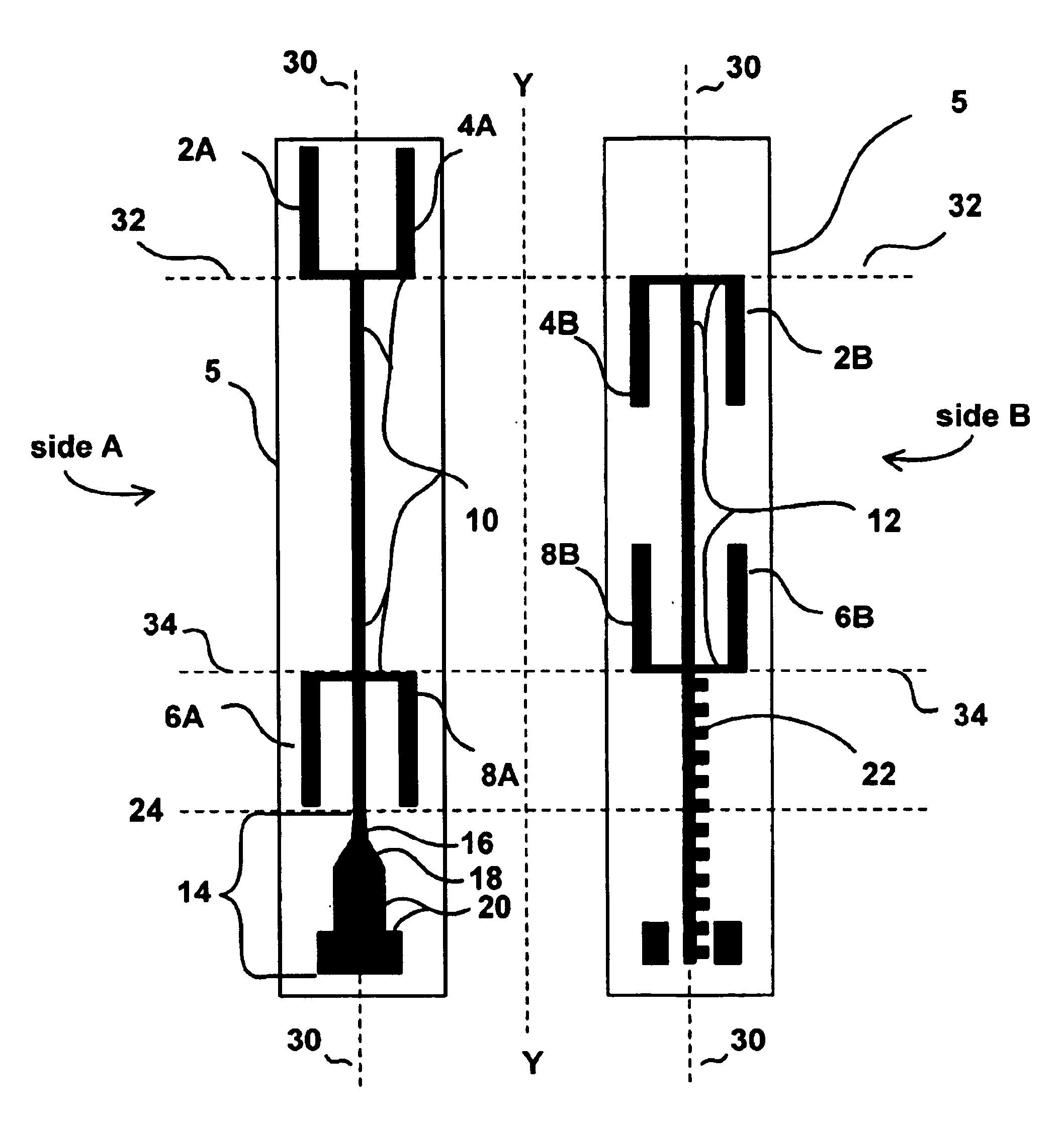
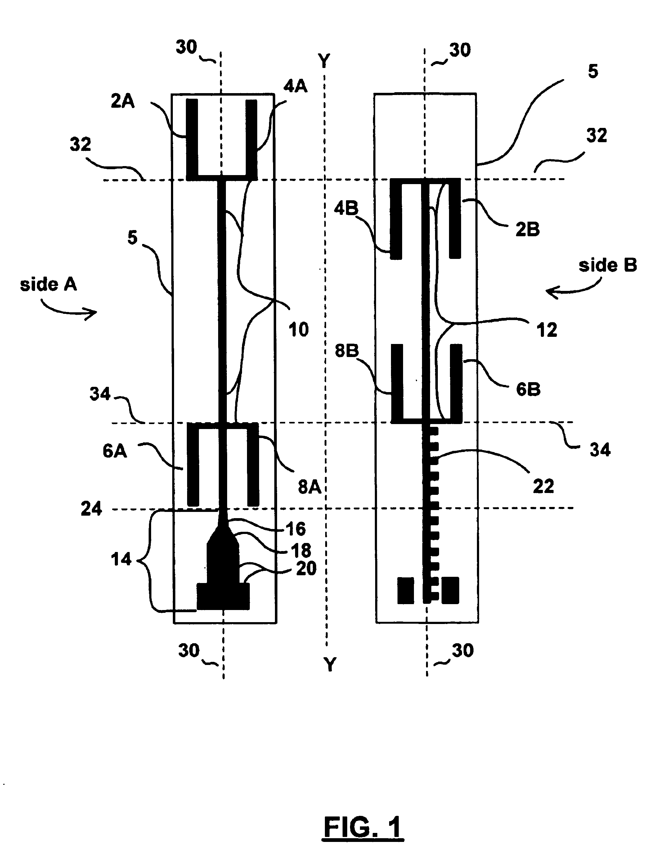
FIG. 1 illustrates a planar antenna 1 having a scalable, half-wavelength multi-dipole structure for receiving and transmitting high-frequency signals. Two sides, Side A and Side B, provide two views of the dielectric substrate 5's opposing sides, flipped along vertical axis Y. Antenna 1 includes two layers of conducting (preferably) metallic strips disposed upon opposing sides of the insulating substrate 5. A plurality of half wavelength dipoles 2, 4, 6, and 8 are positioned in series along feed structures 10 and 12. Each dipole is preferably bifurcated between side A and side B of substrate 5 and each quarter-wavelength dipole half (e.g., 2A and 2B) is separately connected to either of feed structures 10 and 12, respectively. Dipoles 2 and 4 are bifurcated along a horizontal axis 32 and dipoles 6 and 8 are bifurcated along a horizontal axis 34. The dipoles' bifurcation and placement along opposing sides of substrate 5 eliminates the need for additional substrate layers and vias to ...


PUM


Abstract

The present invention provides a planar antenna having a scalable multi-dipole structure for receiving, and transmitting high-frequency signals, including a plurality of opposing layers of conducting strips disposed upon either side of an insulating (dielectric) substrate. The dipoles are bifurcated between sides of a substrate on which the dipoles are disposed. A feed line is balanced to a co-axial cable and feeds one half of the bifurcated dipoles, and an independent feed line is connected to the other half of the bifurcated dipoles. Sets of the dipoles are arranged symmetrically around a center axis of the feed lines. The sets of dipoles are in series with other sets of dipoles. The antenna is ideally suited for operation in the 5.15-5.35 GHz RF band.

Description

BACKGROUND OF THE INVENTION1. Field of InventionThe present invention relates generally to the field of high frequency antennas, and more particularly to the field of high-gain, multi-dipole array antennas constructed using inexpensive manufacturing techniques.2. Discussion of BackgroundThe U.S. Federal Communications Commission (FCC) allocates a certain number of frequency bands where a license is not required for use. For example, many garage-door openers operate in the unlicensed 49 MHz band. Similarly, the unlicensed 2.4 GHz frequency band has become popular for connecting computers to a wireless LAN.Unfortunately, the 2.4 GHz band available in the U.S. and worldwide hosts a myriad of devices and competing communications standards that have led to increasing interference and degraded performance in the wireless networking world. Devices operating at 2.4 GHz include common household items such as microwave ovens, cordless phones and wireless security cameras, in addition to the m...

Claims


Application Information

Patent Timeline
IPC IPC(8): H01Q9/28H01Q9/04H01Q21/06
CPCH01Q9/28H01Q21/062
Inventor LEBARIC, JOVAN E.SHOR, ARIE
Owner QUALCOMM INC
Why Eureka
Try Eureka